6. For a T-CB in a T640 router connected to a TX matrix router, reconnect the cable
previously plugged into the CIP port.
7. Verify that the control board is functioning normally:
•
Check the LEDs on the control board faceplate. The green OK LED should light
steadily a few minutes after the control board is installed. If the FAIL LED is lit
steadily, remove and install the control board again. If the FAIL LED still lights
steadily, the control board is not functioning properly. Contact your customer support
representative.
•
Use the CLI command show chassis environment cb to check the status of the control
board.
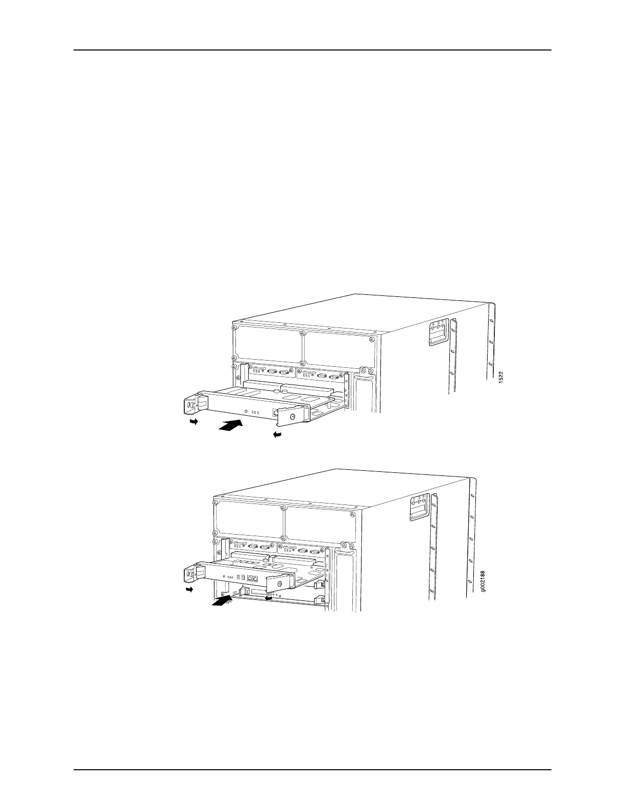
Figure 151: Installing a Standard Control Board
Figure 152: Installing a T-CB
Related
Documentation
T640 Preventing Electrostatic Discharge Damage on page 506•
• T640 Standard Control Boards LEDs on page 64
• T640 Standard Control Boards Description on page 63
• T640 T Series Control Boards (T-CBs) Description on page 64
• T640 T Series Control Boards (T-CBs) LEDs on page 66
Copyright © 2017, Juniper Networks, Inc.316
T640 Core Router Hardware Guide

 Loading...


