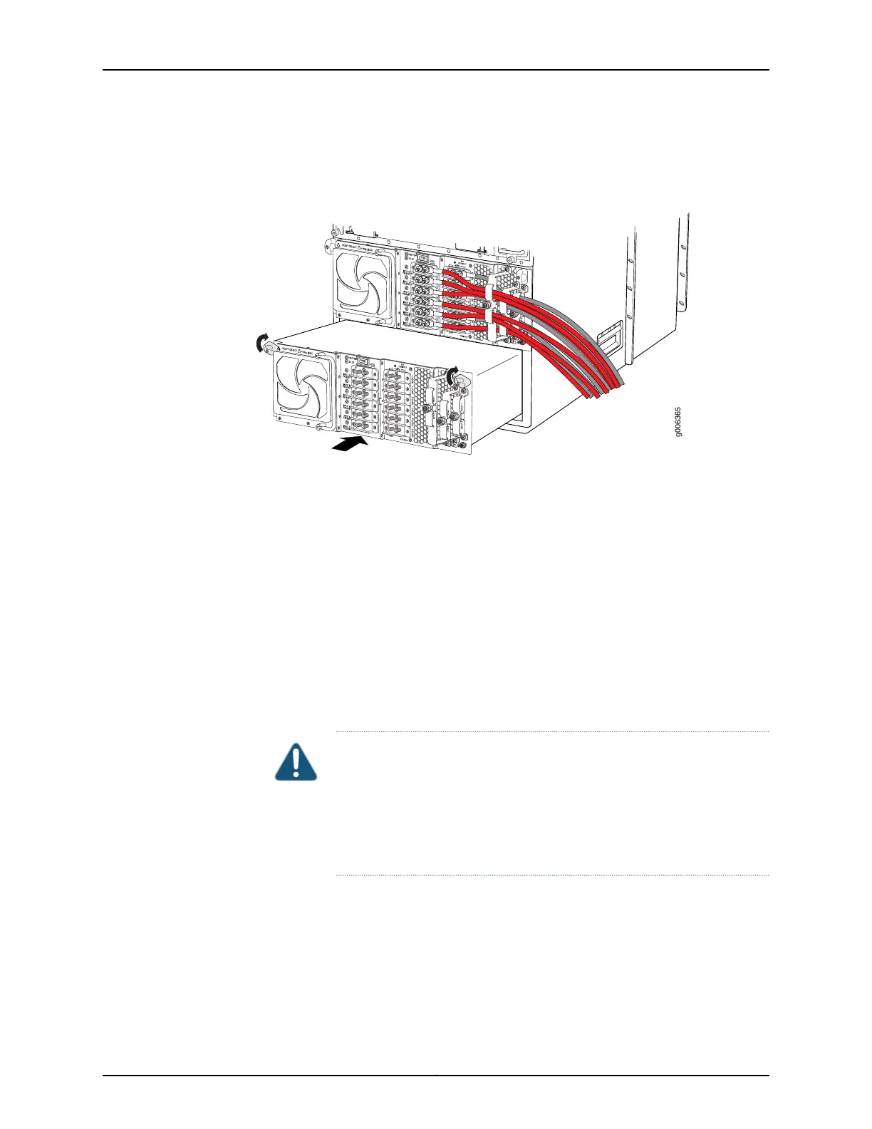
3. Using both hands, slide the power supply into the chassis until you feel resistance
(see Figure 199 on page 384).
Figure 199: Inserting the DC Power Supply into the Chassis
4. Twist the ejector handles at the upper corners of the power supply faceplate clockwise
until they stop.
5. Tighten the captive screws at the lower corners of the power supply faceplate to
secure the power supply in the chassis.
6. Verify that a licensed electrician has attached cable lugs to the power cables that you
supply.
7. Remove the clear plastic cover protecting the terminal studs on the faceplate.
8. Remove the nut and washer from each power terminal stud.
CAUTION: You must ensure that power connections maintain the proper
polarity. The power source cables might be labeled (+) and (–) to indicate
their polarity. There is no standard color coding for DC power cables. The
color coding used by the external DC power source at your site determines
the color coding for the leads on the power cables that attach to the
terminal studs on each power supply.
9. Attach the lugs on the DC source power cables to the terminal studs.
a. Attach the negative (–) DC source power cable lug to the –48V (input) terminal.
b. Attach the positive (+) DC source power cable lug to the RTN (return) terminal.
Copyright © 2017, Juniper Networks, Inc.384
T640 Core Router Hardware Guide

 Loading...


