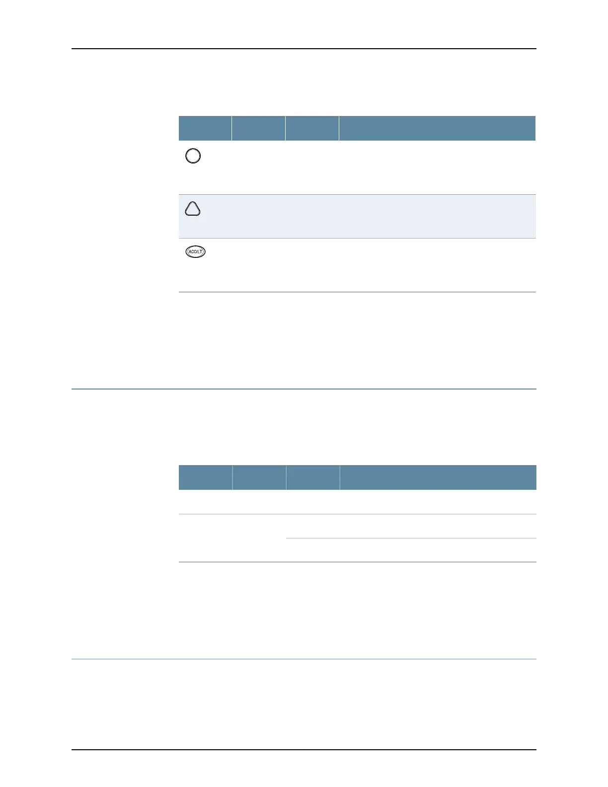
Table 5: Alarm LEDs and Alarm Cutoff/Lamp Test Button
DescriptionStateColorShape
Critical alarm LED—Indicates a critical condition that
can cause the router to stop functioning. Possible
causes include component removal, failure, or
overheating.
On steadilyRed
Warning alarm LED—Indicates a serious but nonfatal
error condition, such as a maintenance alert or a
significant increase in component temperature.
On steadilyYellow
Alarm cutoff/lamp test button—Deactivates red and
yellow alarms. Causes all LEDs on the craft interface
to light (for testing purposes), when pressed and
held.
——
Related
Documentation
T640 Chassis Description on page 15•
• T640 LED Overview on page 464
• Replacing a T640 Craft Interface on page 265
T640 Craft Interface FPC LEDs and Online/Offline Buttons
Each FPC slot has two LEDs that indicate its status. The FPC LEDs, labeled FPC0 through
FPC7, are located along the bottom of the craft interface. Table 6 on page 24 describes
the functions of the FPC LEDs.
Table 6: FPC LEDs
DescriptionStateColorLabel
FPC has failed.On steadilyRedFAIL
FPC is functioning normally.On steadilyGreenOK
FPC is starting up.Blinking
Related
Documentation
T640 Chassis Description on page 15•
• T640 LED Overview on page 464
• Replacing a T640 Craft Interface on page 265
T640 Craft Interface Host Subsystem LEDs
Each host subsystem has three LEDs, located on the upper right of the craft interface,
that indicate its status. The LEDs labeled HOST0 show the status of the Routing Engine
in slot RE0 and the control board in slot CB0. The LEDs labeled HOST1 show the status
Copyright © 2017, Juniper Networks, Inc.24
T640 Core Router Hardware Guide

 Loading...


