To add a message that alternates every 2 seconds with the default status messages,
use the set chassis display message command. For more information, see set chassis
display message.
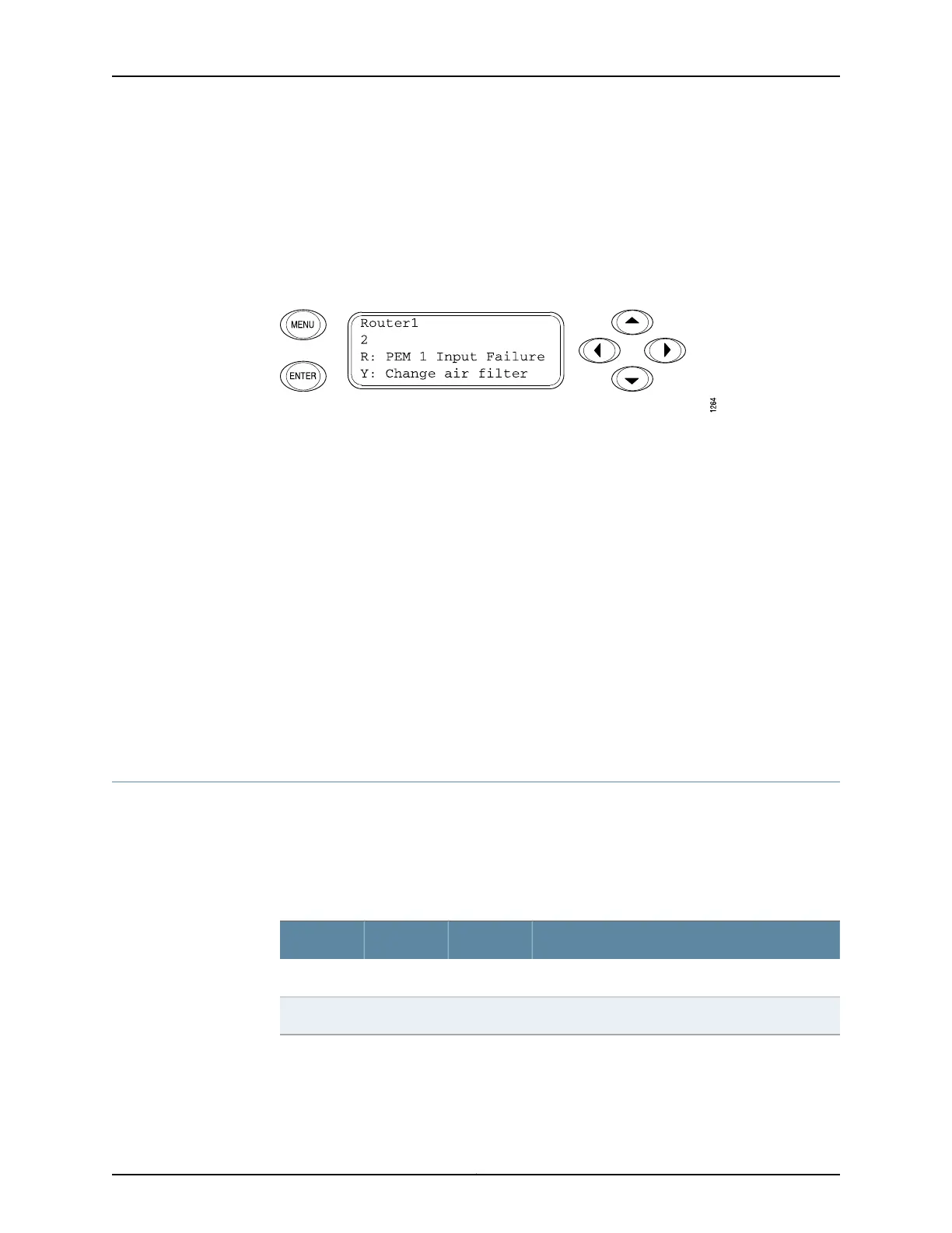
When a red or yellow alarm occurs, the LCD switches to alarm mode and reports the
alarm condition, as shown in Figure 11 on page 26.
Figure 11: T640 LCD in Alarm Mode
The lines in the display report the following information:
•
First line—Router name.
•
Second line—Number of active alarms.
•
Third and fourth lines—Individual alarm messages, with the most severe condition
shown first. The prefix on each line indicates whether the alarm is a red (R) or yellow (Y)
alarm.
For an overview of alarm messages that can appear on the LCD, see “T640 Alarm
Messages Overview” on page 466.
Related
Documentation
T640 Chassis Description on page 15•
• T640 LED Overview on page 464
• Replacing a T640 Craft Interface on page 265
T640 Craft Interface SIB LEDs
Each SIB has two LEDs on the craft interface that indicate its status. The SIB LEDs, labeled
SIB0 through SIB2, are located on the upper right of the craft interface. The ACTIVE LED
on the SIB faceplate is not replicated on the craft interface. Table 8 on page 26 describes
the functions of the SIB LEDs.
Table 8: SIB LEDs on the Craft Interface
DescriptionStateColorLabel
SIB has failed.On steadilyRedFAIL
SIB is functioning normally.On steadilyGreenOK
Related
Documentation
T640 Chassis Description on page 15•
• T640 LED Overview on page 464
Copyright © 2017, Juniper Networks, Inc.26
T640 Core Router Hardware Guide

 Loading...


