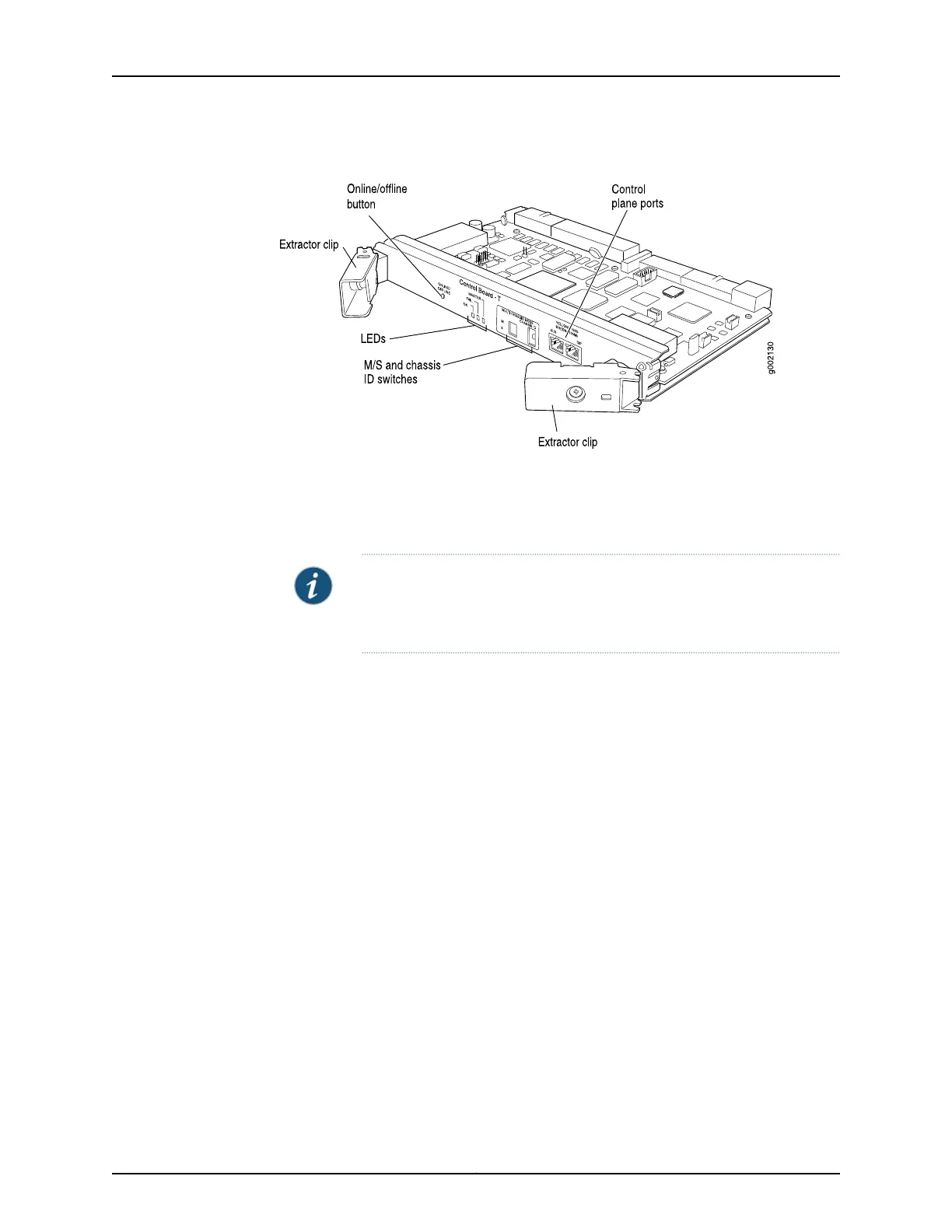
Figure 26: T-CB
The following components are located on the T-CB faceplate:
•
The MASTER, FAIL, and OK LEDs, which indicate the status of the T-CB.
•
Online/offline button.
NOTE: When the adjacent Routing Engine is online, the online/offline
button on the T-CB faceplate is nonfunctional. For more information, see
“Taking the T640 Host Subsystem Offline” on page 307.
•
Two RJ-45 ports labeled AUX and CIP on the T-CB faceplate.
For T640 routers connected to a TX Matrix platform, only the CIP port is used. For more
information, see the TX Matrix Router Hardware Guide.
•
The M/S and CHASSIS ID configuration switches.
•
For a standalone T640 router, the M/S and CHASSIS ID configuration switches must
always be set to S and 0.
•
For T640 routers connected to a TX Matrix platform, the M/S and CHASSIS ID
configuration switches must always be set to M and the chassis identifier (ID) of the
router. In this case, both T-CBs must have the same chassis ID. For more information,
see the TX Matrix Router Hardware Guide.
Related
Documentation
T640 Hardware Component Overview on page 13•
• T640 Host Subsystem Description on page 35
• T640 Control Boards Description
• T640 T Series Control Boards (T-CBs) LEDs on page 66
65Copyright © 2017, Juniper Networks, Inc.
Chapter 5: Host Subsystem Components and Descriptions

 Loading...


