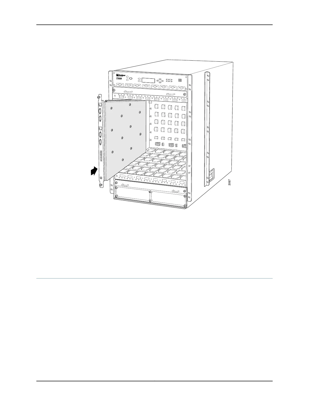
Figure 118: Installing a CIP
Related
Documentation
T640 Preventing Electrostatic Discharge Damage on page 506•
• T640 Connector Interface Panel (CIP) Description on page 19
• Connecting the T640 Router to a Management Console or Auxiliary Device on page 210
• Replacing the T640 Connections to Routing Engine Interface Ports
• T640 Routing Engine Interface Cable and Wire Specifications on page 145
Replacing the T640 Alarm Relay Wires
To connect the router to external alarm-reporting devices, attach wires to the RED ALARM
and YELLOW ALARM relay contacts on the CIP. A system condition that triggers the red
or yellow alarm LED on the craft interface also activates the corresponding alarm relay
contact.
The terminal blocks that plug into the alarm relay contacts are supplied with the router.
They accept wire of any gauge between 28-AWG and 14-AWG (0.08 and 2.08 mm
2
),
which is not provided. Use the wire gauge appropriate for the external device you are
connecting.
Copyright © 2017, Juniper Networks, Inc.270
T640 Core Router Hardware Guide

 Loading...


