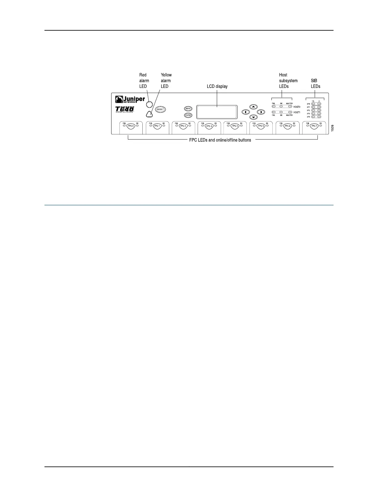
Figure 9: Front Panel of the T640 Craft Interface
Related
Documentation
T640 Chassis Description on page 15•
• T640 Hardware Component Overview on page 13
• Replacing a T640 Craft Interface on page 265
T640 Craft Interface Alarm LEDs and ACO/LT Button
Two large alarm LEDs are located at the upper left of the craft interface (see Figure 9
on page 23). The circular red LED lights to indicate a critical condition that can result in
a system shutdown. The triangular yellow LED lights to indicate a less severe condition
that requires monitoring or maintenance. Both LEDs can be lit simultaneously.
A condition that causes an LED to light also activates the corresponding alarm relay
contact on the connector interface panel (CIP), as described in “T640 Connector Interface
Panel (CIP) Description” on page 19. The LCD on the craft interface reports the cause of
the alarm, as described in “T640 Craft Interface LCD and Navigation Buttons” on page 25.
To deactivate red and yellow alarms, press the button labeled ACO/LT (for “alarm
cutoff/lamp test”), which is located to the right of the alarm LEDs. Deactivating an alarm
turns off both LEDs and deactivates the device attached to the corresponding alarm
relay contact on the CIP. However, the LCD continues to report the alarm message until
you clear the condition that caused the alarm.
Table 5 on page 24 describes the alarm LEDs and alarm cutoff button in more detail.
23Copyright © 2017, Juniper Networks, Inc.
Chapter 3: Chassis Components and Descriptions

 Loading...


