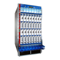
Table 89: Field-Replaceable Units
Hot-Pluggable FRUsHot-Removable and Hot-Insertable FRUs
Connector Interface Panel (CIP)
Nonredundant control board
Master control board (if nonstop active routing
is not configured)
Nonredundant Routing Engine
Master Routing Engine (if nonstop active routing
is not configured)
Master and nonredundant SCGs
Air filters
Craft Interface
Flexible PIC Concentrators (FPCs)
Front and rear fan trays
Physical Interface Cards (PICs)
Power supplies
Backup SONET Clock Generators (SCGs)
Switch Interface Boards (SIBs)
Master control board (if nonstop active routing
is configured)
Backup control board
Backup Routing Engine
Related
Documentation
T640 Router Description on page 3•
• Taking the T640 Host Subsystem Offline on page 307
Tools and Parts Required to Replace the T640 Hardware Components
To replace hardware components, you need the tools and parts listed in
Table 90 on page 262.
Table 90: Tools and Parts Required for Component Replacement
Tool or PartComponents
Electrostatic discharge (ESD) grounding wrist
strap
All
Phillips (+) screwdriver, number 2
1/4-in. slotted screwdriver or 5/32-in. (4 mm)
allen wrench
NOTE: The terminal connections have either
slotted screws or hex screws. Use a 1/4-in.
slotted screwdriver for the slotted screws. Use
a 5/32-in (4-mm) Allen wrench for the 5/16-in
hex screws.
AC power supply
Copyright © 2017, Juniper Networks, Inc.262
T640 Core Router Hardware Guide

 Loading...