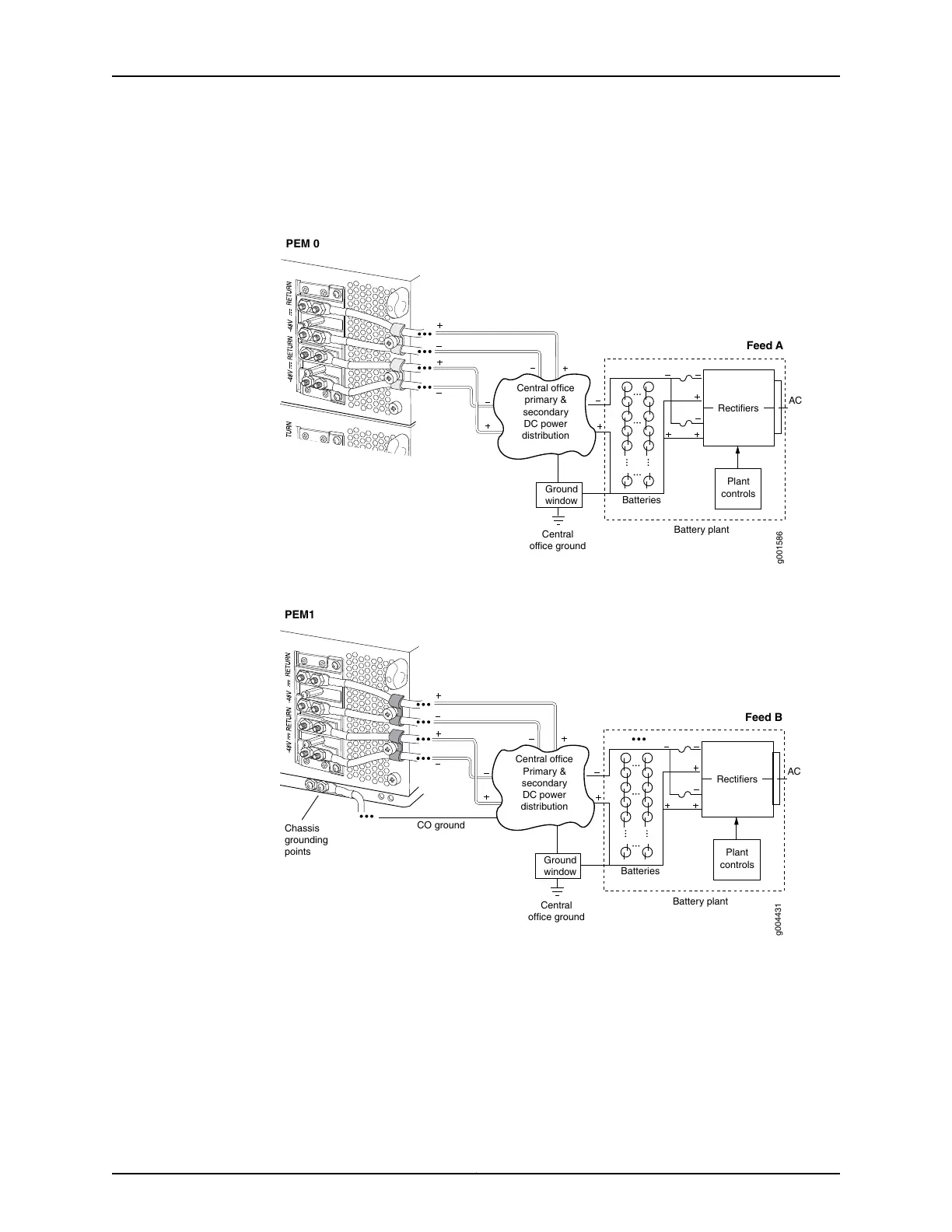
Figure 54 on page 131 and Figure 55 on page 131 shows a typical DC source cabling
arrangement.
Figure 54: Typical DC Source Cabling from PEM0 to Feed A
Ground
window
AC
Central
office ground
PEM 0
Feed A
Plant
controls
Rectifiers
Battery plant
Batteries
g001586
Central office
primary &
secondary
DC power
distribution
Figure 55: Typical DC Source Cabling from PEM1 to Feed B
Ground
window
AC
Central
office ground
Chassis
grounding
points
PEM1
Feed B
CO ground
Plant
controls
Rectifiers
Battery plant
Batteries
g004431
Central office
Primary &
secondary
DC power
distribution
Related
Documentation
T640 Power System Description on page 95•
• T640 DC Power System Electrical Specifications on page 125
• T640 DC Power Supply Electrical Specifications on page 126
• T640 General Electrical Safety Guidelines and Electrical Codes on page 529
131Copyright © 2017, Juniper Networks, Inc.
Chapter 10: DC Power Requirements and Specifications

 Loading...


