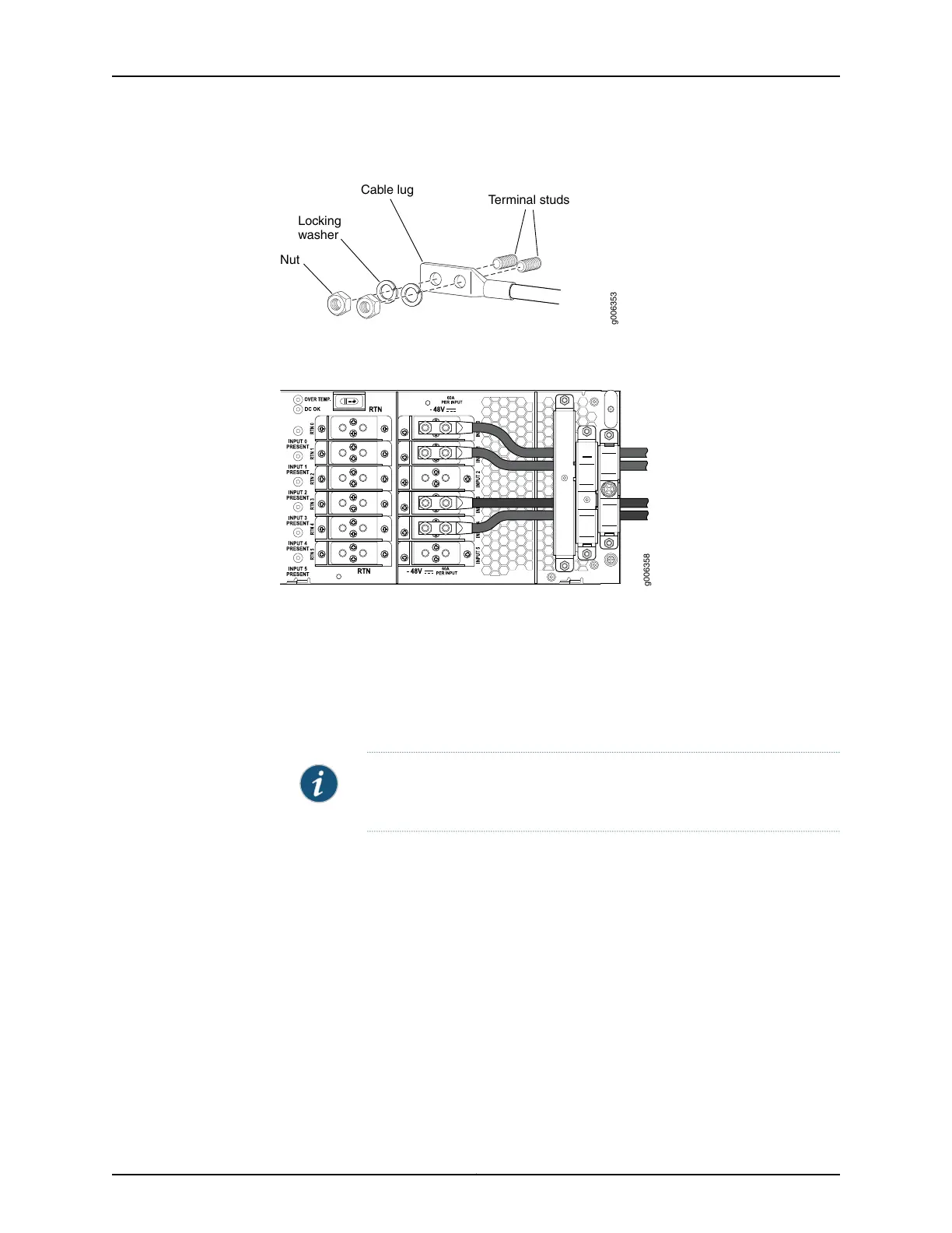
Figure 109: Connecting DC Power Cables
g006353
Terminal studs
Cable lug
Locking
washer
Nut
Figure 110: Connecting Negative (–) DC Power Cables to INPUT 0, INPUT 1,
INPUT 3, and INPUT 4
8. Replace the smallest cable restraint on the far right, and tighten the captive screw to
hold the power cables for INPUT 0, INPUT 1, INPUT 3, and INPUT 4 in place.
9. Route the positive (+) DC source power cables for RTN 0, RTN 1, RTN 3, and RTN 4
over the largest cable restraint on the left. The left cable restraint is marked as follows
from top to bottom RTN 0, RTN 1, RTN 3, and RTN 4.
NOTE: You must route the cables as marked to be able to replace the
clear plastic cover over the terminal studs.
Attach the negative (–) DC source power cable lugs to the RTN terminals on the left:
RTN 0, RTN 1, RTN 3, and RTN 4. Secure the cable lugs to the terminal studs, first with
the washers, then with the nuts. Using a 7/16-in. (11 mm) nut driver, tighten the nuts.
Apply between 23 lb-in. (2.6 Nm) and 25 lb-in. (2.8 Nm) of torque to each nut.
10. Replace the left cable restraint, and tighten the captive screw to hold the power cables
for RTN 0, RTN 1, RTN 3, and RTN 4 in place.
Copyright © 2017, Juniper Networks, Inc.238
T640 Core Router Hardware Guide

 Loading...


