•
Two configuration switches—M/S and CHASSIS ID—that must be set to S and 0 for
standalone T640 routers.
•
RJ-45 ports labeled SFC0 through SFC5, which are not currently supported on the
T640 router. Two LEDs for each port—labeled LINK and ACT— are also not supported.
•
One JCS port, which is not supported on the T640 router. The LINK LED indicates the
status of the port.
Related
Documentation
T640 Hardware Component Overview on page 13•
• T640 Host Subsystem Description on page 35
• T640 Control Boards Description
• T640 LCC-CB LEDs on page 62
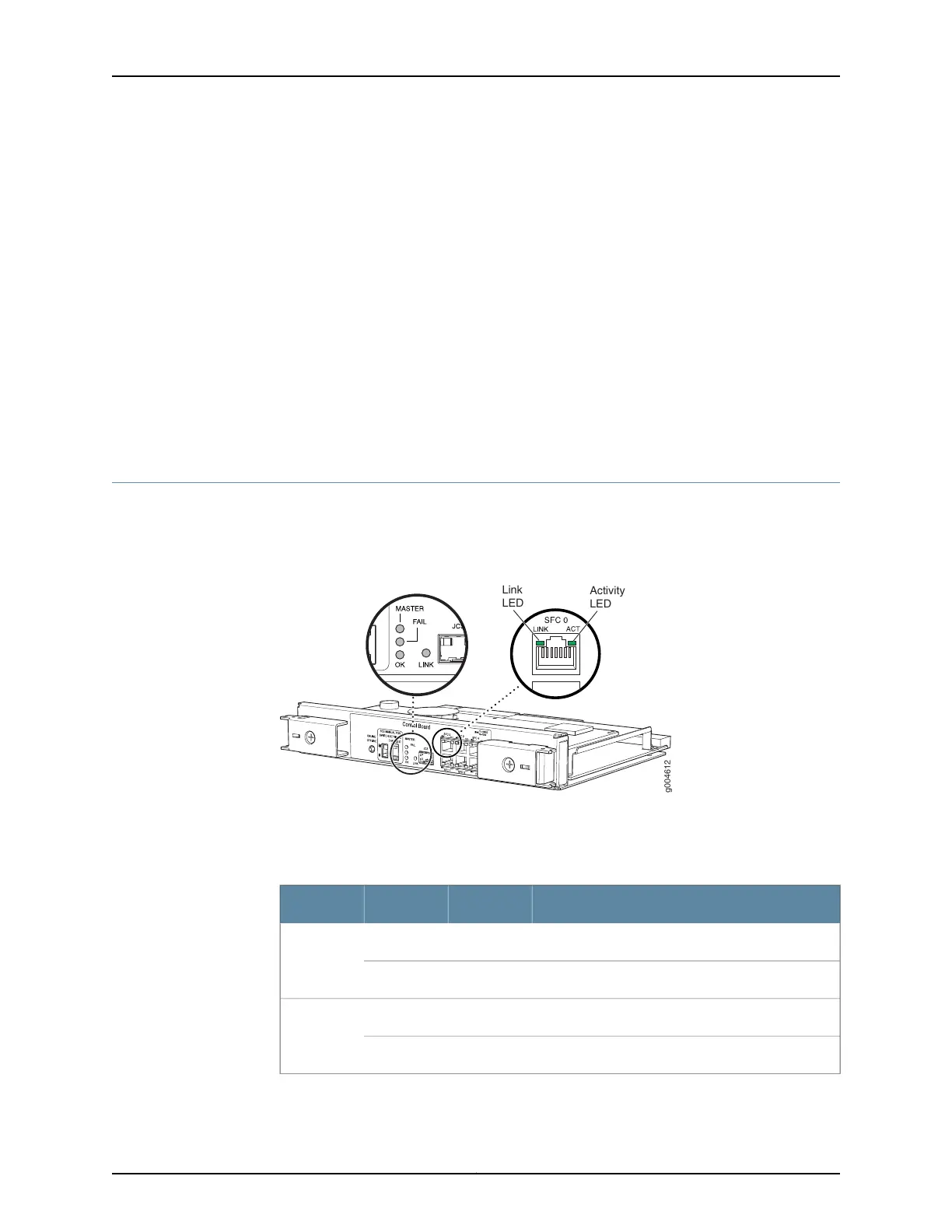
T640 LCC-CB LEDs
Status LEDs and port LEDs are located on the faceplate of the LCC-CB (see
Figure 24 on page 62).
Figure 24: LCC-CB LEDs
g004612
Link
LED
Activity
LED
The LEDs located in the middle of the LCC-CB indicate its status.Table 40 on page 62
describes the functions of the LCC-CB LEDs.
Table 40: LCC-CB LEDs
DescriptionStateColorLabel
LCC-CB is functioning as the master.On steadilyBlueMASTER
LCC-CB is functioning as the backup.Off–
LCC-CB has failed.On steadilyYellowFAIL
No faults have been detected on the LCC-CB.Off–
Copyright © 2017, Juniper Networks, Inc.62
T640 Core Router Hardware Guide

 Loading...


