feeds derived from feed B. This configuration provides the commonly
deployed A/B feed redundancy for the system.
7. Loosen the captive screws on the cable restraint on the right edge of the power supply
faceplate (using a Phillips (+) screwdriver, number 2).
8. Route the positive and negative DC power cables through the cable restraint.
9. Tighten the cable restraint captive screws to hold the power cables in place.
10. Verify that the power cabling is correct, that the power cables are not touching or
blocking access to router components, and that they do not drape where people could
trip on them.
11. Replace the clear plastic cover over the terminal studs on the faceplate.
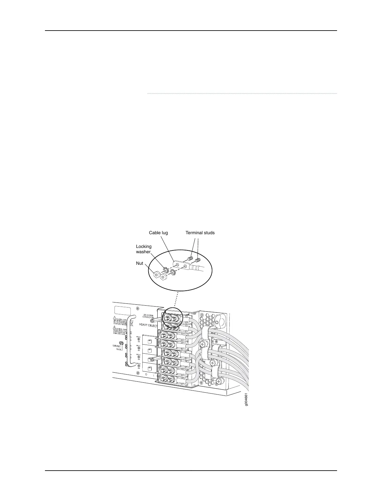
Figure 100: Connecting Power to the Four-Input 240-A DC Power Supply
g004661
Terminal studsCable lug
Locking
washer
Nut
Related
Documentation
T640 Power System Description on page 95•
• T640 DC Power Distribution on page 130
Copyright © 2017, Juniper Networks, Inc.226
T640 Core Router Hardware Guide

 Loading...


