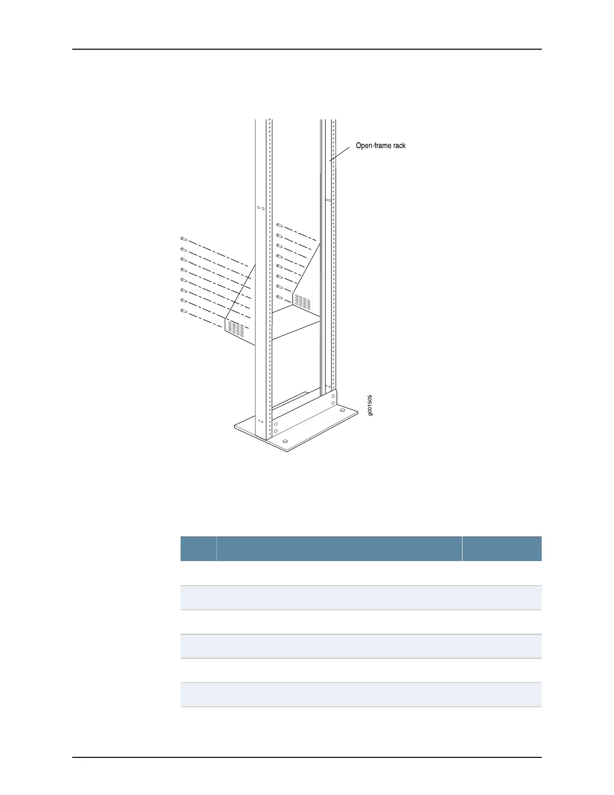
Figure 62: Installing the Mounting Hardware for an Open-Frame Rack
Table 88 on page 164 specifies the mounting holes in which you insert the mounting screws
(an X indicates a mounting hole location), and cage nuts if needed. The hole distances
are relative to one of the standard U divisions on the rack. For reference, the bottom of
all mounting shelves is at 0.04 in. (0.02 U) above a U division.
Table 88: T640 Open-Frame Rack Mounting Hole Locations
Large ShelfDistance Above U DivisionHole
X19.50 U34.13 in. (86.7 cm)59
X17.50 U30.63 in. (77.8 cm)53
X16.50 U28.88 in. (73.3 cm)50
X14.50 U25.38 in. (64.5 cm)44
X13.50 U23.63 in. (60.0 cm)41
X11.50 U20.13 in. (51.1 cm)35
Copyright © 2017, Juniper Networks, Inc.164
T640 Core Router Hardware Guide

 Loading...


