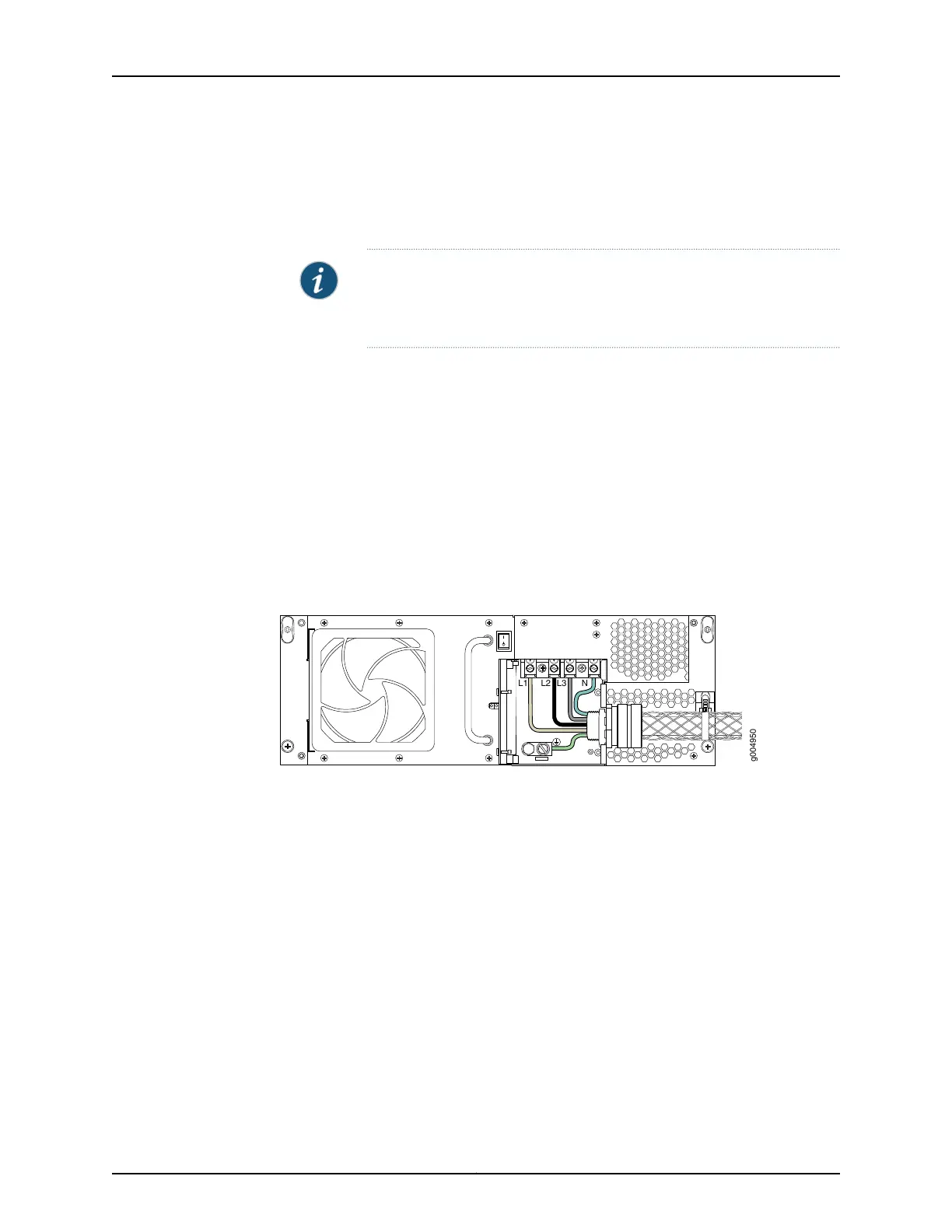
11. Connect the AC power cord wires to ground and the AC terminal block on the
three-phase wye AC power supply (Figure 225 on page 419). Loosen each of the input
terminals or grounding point screws, insert each wire into the grounding point or input
terminal, and tighten the screw.
NOTE: The terminal connectionshaveeither slotted screws or hex screws.
Use a 1/4-in. slotted screwdriver for the slotted screws. Use a 5/32-in
(4-mm) Allen wrench for the 5/16-in hex screws.
a. Insert the wire labeled GND into the grounding point labeled GND.
b. Insert the wire L1 into the L1 input terminal.
c. Insert the wire labeled L2 into the L2 input terminal.
d. Insert the wire labeled L3 into the L3 input terminal.
e. Insert the wire labeled N into the N input terminal
Figure 225: Connecting Power to the Wye 3–Phase AC Power Supply
12. Verify that the power cord wire connections are correct.
13. Using a number 2 Phillips (+) screwdriver, tighten the two captive screws on the metal
AC wiring compartment.
14. Place the AC power cord into the plastic tie located on the right side of the power
supply, and fasten the plastic tie.
15. Verify that the AC power cord is not touching or blocking access to router components,
and that it does not drape where people could trip on it.
16. Remove the ESD grounding strap from the ESD points on the chassis. Connect the
strap to an approved site ESD grounding point. See the instructions for your site.
419Copyright © 2017, Juniper Networks, Inc.
Chapter 29: Replacing Power System Components

 Loading...


