10. Screw the retaining nut onto the AC power cord to secure it to the metal wiring
compartment.
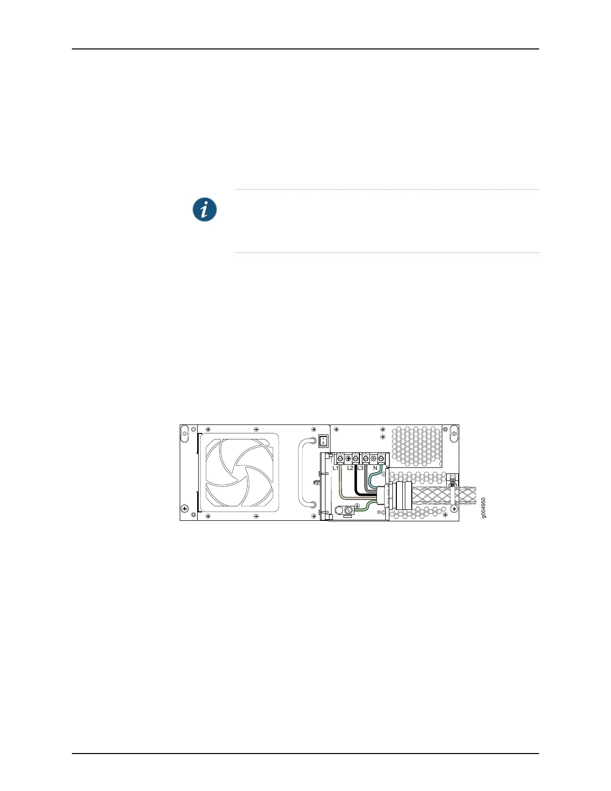
11. Connect the wires to the AC terminal block on the three-phase wye AC power supply
(Figure 113 on page 245). Loosen each of the input terminals or grounding point screws,
insert each wire into the grounding point or input terminal, and tighten the screw.
NOTE: The terminal connectionshaveeither slotted screws or hex screws.
Use a 1/4-in. slotted screwdriver for the slotted screws. Use a 5/32-in
(4-mm) Allen wrench for the 5/16-in hex screws.
a. Insert the wire labeled GND into the grounding point labeled GND.
b. Insert the wire labeled L1 into the L1 input terminal.
c. Insert the wire labeled L2 into the L2 input terminal.
d. Insert the wire labeled L3 into the L3 input terminal.
e. Insert the wire labeled N into the N input terminal
Figure 113: Connecting Power to the Three-Phase Wye AC Power Supply
12. Verify that the power cable connections are correct.
13. Using a number 2 Phillips (+) screwdriver, tighten the two captive screws on the metal
AC wiring compartment.
14. Use the provided plastic cable tie to fasten the AC power cord to the power supply.
245Copyright © 2017, Juniper Networks, Inc.
Chapter 22: Providing Power to the T640

 Loading...


