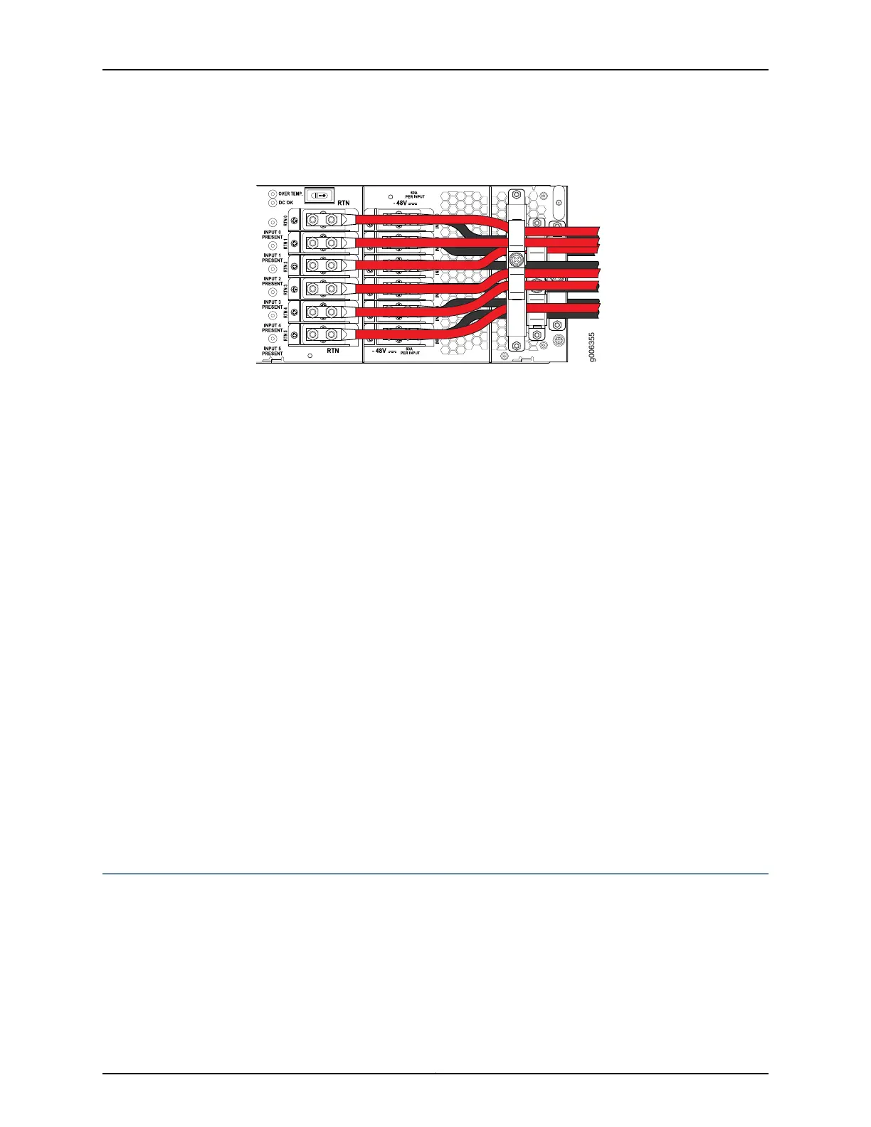
Figure 104: Connecting Positive (+) DC Power Cables to RTN 2, RTN 5,
RTN 0, RTN 1, RTN 3, and RTN 4
15. Verify that the power cabling is correct, that the power cables are not touching or
blocking access to router components, and that they do not drape where people could
trip on them.
16. Replace the clear plastic cover over the terminal studs on the faceplate.
Related
Documentation
Tools and Parts Required to Provide Power to the T640 Router on page 219•
• Connecting DC Power to the T640 Router (Four 60-A Inputs to Six-Input DC Power
Supplies) on page 236
• Connecting DC Power to the T640 Router (Five 60-A Inputs to Six-Input DC Power
Supplies) on page 231
• Powering On the T640 Router
• Configuring DC Power on a T640 Router on page 255
• Troubleshooting the T640 Power System on page 476
• T640 DC Power System Requirements on page 128
• T640 DC Power Cable and Lug Specifications on page 132
• T640 General Electrical Safety Guidelines and Electrical Codes on page 529
• Site Electrical Wiring Guidelines for Juniper Networks Devices on page 538
Connecting DC Power to the T640 Router (Five 60-A Inputs to Six-Input DC Power
Supplies)
You connect DC power to the router by attaching power cables from the DC power sources
to the terminal studs on the power supply faceplates. You must provide power cables
(the cable lugs are supplied with the router).
231Copyright © 2017, Juniper Networks, Inc.
Chapter 22: Providing Power to the T640

 Loading...


