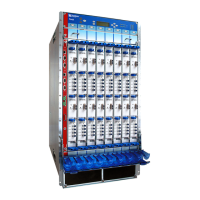
1. Place an electrostatic bag or antistatic mat on a flat, stable surface.
2. Attach an electrostatic discharge (ESD) grounding strap to your bare wrist, and connect
the strap to an approved site ESD grounding point. See the instructions for your site.
3. Before removing the FPCs, record their location in the chassis so that you can reinstall
each FPC in the correct slot.
4. If you are removing a Type 2 FPC or Type 3 FPC, loosen the screws inside the ejector
handles at the top and bottom of the FPC faceplate.
5. Simultaneously turn both the ejector handles counterclockwise to unseat the FPC.
6. Grasp the handles and slide the FPC straight out of the card cage halfway.
7. Place one hand around the front of the FPC (the PIC housing) and the other hand
under it to support it. Slide the FPC completely out of the chassis, and place it on the
antistatic mat or in the electrostatic bag.
CAUTION: The weight of the FPC is concentrated in the back end. Be
prepared to accept the full weight—up to 32 lb (14.5 kg)—as you slide the
FPC out of the chassis.
When the FPC is out of the chassis, do not hold it by the ejector handles
or edge connectors. They cannot support its weight.
Do not stack FPCs on top of one another after removal. Place each one
individually in an electrostatic bag or on its own antistatic mat on a flat,
stable surface.
8. Repeat the procedure for each remaining FPC.
189Copyright © 2017, Juniper Networks, Inc.
Chapter 19: Installing the T640 Router Without a Mechanical Lift

 Loading...