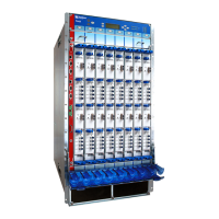
Table 3: T640 Hardware Components (continued)
DescriptionHardware Model NumberComponent
“T640 Cooling System Description” on page 31FAN-REAR-TX-T640
FAN-REAR-TXP-LCC
FAN-T-FBOT
FAN-T-FTOP
FLTR-KIT-T640
Cooling system, including fan trays
and air filters
“T640 Craft Interface Description” on page 22CIP-L-T640Connector interface panel (CIP)
T640 Control Boards Description
“T640 Standard Control Boards Description” on
page 63
“T640 T Series Control Boards (T-CBs)
Description” on page 64
“T640 LCC-CB Description” on page 61
CB-L-T
CB-T
CB-LCC
Control board
“T640 Craft Interface Description” on page 22CRAFT-T640Craft interface
“T640 FPC Description” on page 67“T640 FPCs Supported” on page 77FPC
“T640 Host Subsystem Description” on page 35See control board and Routing
Engine.
Host subsystem, including control
board and Routing Engine
“T640 Midplane Description” on page 17N/AMidplane
“T640 PIC Description” on page 79T640 Core Router Interface Module
Reference
PIC
“T640 Power System Description” on page 95
“T640 Two-Input 160-A DC Power Supply
Description” on page 96
“T640 Three-Input 240-A DC Power Supply
Description” on page 99
“T640 Four-Input 240-A DC Power Supply
Description” on page 102
“T640 Six-Input DC Power Supply Description”
on page 104
“T640 Three-Phase Delta and Wye AC Power
Supply Description” on page 106
PWR-T-10KW-DELTA-AC
PWR-T-10KW-WYE-AC
PWR-T-DC
PWR-T1600-3-80-DC
PWR-T1600-4-60-DC
PWR-T-6-60-DC
Power system
Copyright © 2017, Juniper Networks, Inc.14
T640 Core Router Hardware Guide

 Loading...