Serial bus analysis
R&S
®
RTM3000
293User Manual 1335.9090.02 ─ 09
The instrument captures and decodes the signal according to the protocol definition
and the configuration settings.
The color-coding of the various protocol sections and errors simplifies the interpretation
of the visual display. The decode information condenses or expands, depending on the
horizontal scale. Various data formats are available to show the result values.
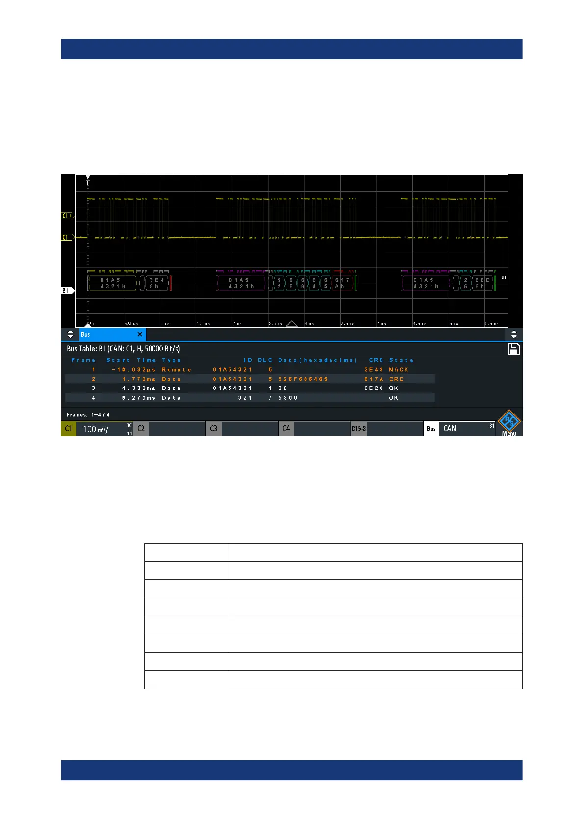
Figure 13-24: Decoded CAN signal with bus table, trigger on frame start
violet = identifier
gray = DLC, data length code
blue = data words
red = error occurred, error frame
The figure above shows a decoded CAN signal and the "Bus Table".
Table 13-4: Content of the CAN frame table
Column Description
Time Diff. Time of frame start in relation to the trigger point
Type Frame type: Data, Remote, Error, or Overload
ID Identifier value, hexadecimal value
DLC Data length code, number of data bytes
Data Hexadecimal values of the data bytes
CRC Hexadecimal value of the Cyclic Redundance Check (checksum)
State Overall state of the frame.
CAN (option R&S RTM-K3)
 Loading...


