Serial bus analysis
R&S
®
RTM3000
270User Manual 1335.9090.02 ─ 09
Address types: 7-bit and 10-bit
Slave addresses can be 7 bits or 10 bits long. A 7-bit address requires 1 byte, 7 bits for
the address followed by the R/W bit.
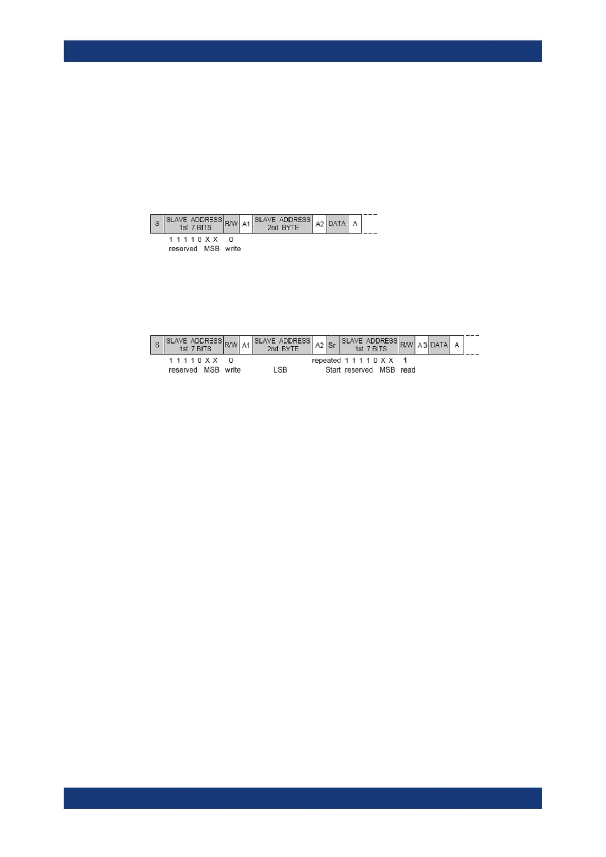
A 10-bit address for write access requires 2 bytes: the first byte starts with the reserved
sequence 11110, followed by the two MSB of the address and the write bit. The second
byte contains the remaining 8 LSB of the address. The slave acknowledges each
address byte.
Figure 13-10: 10-bit address, write access
A 10-bit address for read access requires 3 bytes. The first 2 bytes are identical to the
write access address. The third byte repeats the address bits of the first byte and sets
the read bit.
Figure 13-11: 10-bit address, read access
Trigger
The R&S RTM3000 can trigger on various parts of I²C messages. The data and clock
lines must be connected to the input channels, triggering on math and reference wave-
forms is not possible.
You can trigger on:
●
Start or stop condition
●
Repeated start condition
●
Transfer direction (read or write)
●
Bytes with missing acknowledge bit
●
Specific slave address
●
Specific data pattern in the message
13.3.2 I²C configuration
The correct setup of the protocol parameters and the threshold is the condition for
decoding the signal.
To set up and decode an I²C signal
1. Press the [Protocol] key in the Analysis area of the front panel.
2. Select the bus that you want to use: B1, B2, B3 or B4.
I²C (option R&S
RTM-K1)
 Loading...


