Serial bus analysis
R&S
®
RTM3000
271User Manual 1335.9090.02 ─ 09
3. Select the "Bus Type" = I2C.
4. Select "Configuration".
5. Select the "SCL", the channel to which the clock line is connected.
6. Select the "SDA", the channel to which the data line is connected.
7. Set the threshold. Use one of these methods:
● Tap "Find Threshold". The instrument evaluates the signal and sets the thresh-
old.
● Enter the threshold value in the numeric field.
8. In the "Bus" menu, enable "Decode".
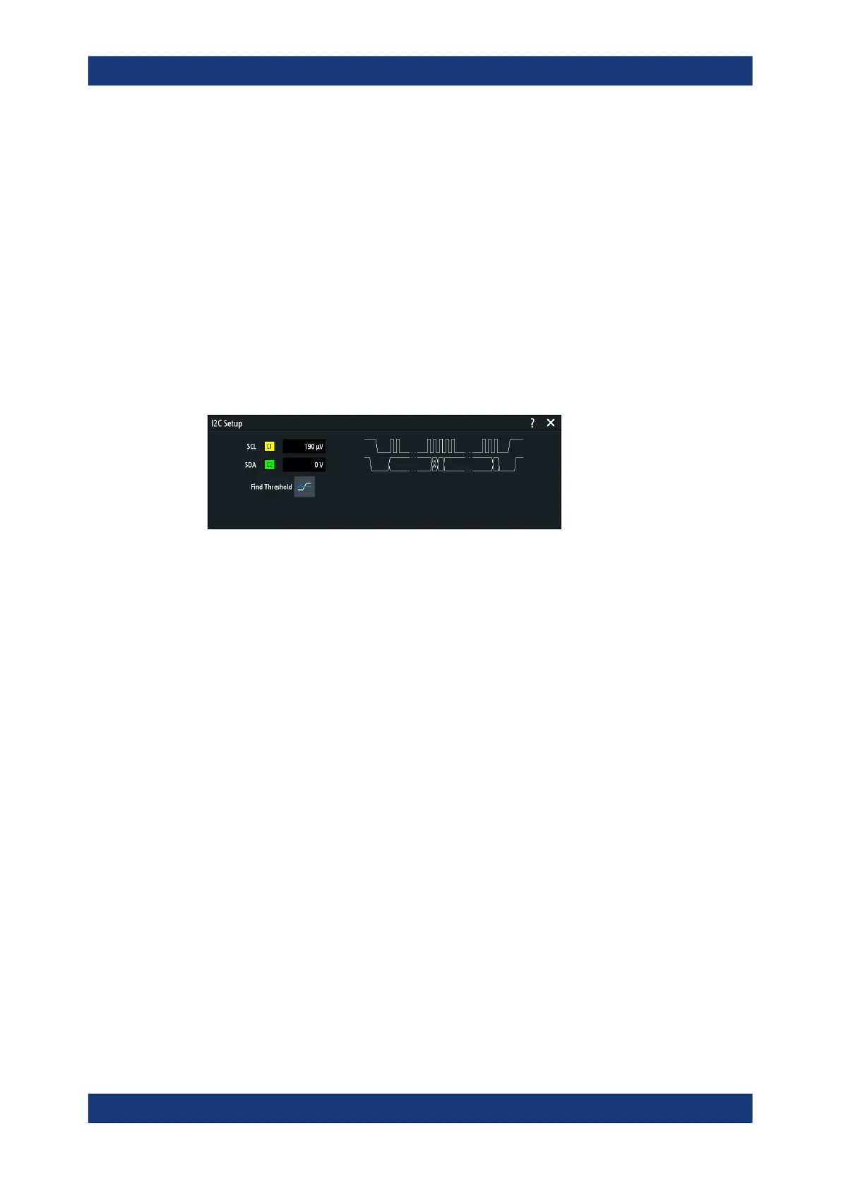
I²C configuration settings
Figure 13-12: I2C setup dialog
SCL............................................................................................................................. 271
SDA.............................................................................................................................271
Threshold, Find Threshold.......................................................................................... 271
SCL
Selects the source channel to which the clock line is connected.
If the MSO option R&S RTM-B1 is installed, you can use logic channels as source.
Remote command:
BUS<b>:I2C:CLOCk:SOURce on page 619
SDA
Selects the source channel to which the data line is connected.
If the MSO option R&S RTM-B1 is installed, you can use logic channels as source.
Remote command:
BUS<b>:I2C:DATA:SOURce on page 619
Threshold, Find Threshold
Set the signal threshold for the source channel. Enter a value, or use "Find Threshold"
to set the threshold to the middle reference level of the measured amplitude.
For analog channels, you can find the value also in the "Vertical" menu > "Chan-
nel <n>" > "Threshold"
For logic channels, you can find the value also in the "Logic" menu > "Technology".
I²C (option R&S
RTM-K1)