Signal generation (option R&S RTM-B6)
R&S
®
RTM3000
420User Manual 1335.9090.02 ─ 09
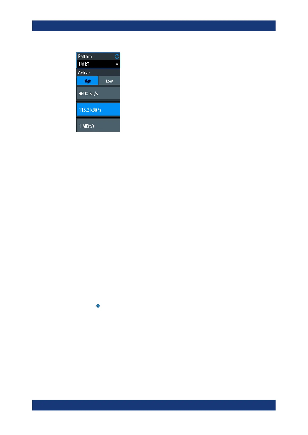
Data Rate
Select the data rate of the bus signal.
The following values are available for the specific bus:
●
UART: 9600 Bit/s, 115.2 kBit/s, 1 MBit/s
●
SPI: 100 kBit/s, 250 kBit/s, 1 MBit/s
●
I2C: 100 kBit/s, 400 kBit/s, 1000 kBit/s, 3400 kBit/s
●
CAN: 50 kBit/s, 100 kBit/s, 1 MBit/s
●
LIN: 9.6 kBit/s, 10.417 kBit/s, 19.200 kBit/s
Active
Sets the polarity for the UART bus.
16.2.7 Settings for PWM signals
You can use the pattern generator to generate several pulse width modulated (PWM)
signals: PWM, PWM - RGB LED, PWM-TestSignals.
● PWM signals......................................................................................................... 420
● PWM - RGB LED signals...................................................................................... 421
● PWM test signals.................................................................................................. 422
16.2.7.1 PWM signals
Access: "Menu" > "Pattern Gen." > "Pattern" = "PWM"
You can use the generated signal to control a motor driver directly, for example.
Frequency
Sets the frequency of the PWM signal.
Remote command:
PGENerator:PATTern:FREQuency on page 790
Duty Cycle
Sets the duty cycle of the PWM signal at P0. Change the duty cycle using the Naviga-
tion knob to increase or decrease the motor speed.
Pattern generator
 Loading...


