Signal generation (option R&S RTM-B6)
R&S
®
RTM3000
422User Manual 1335.9090.02 ─ 09
Intens
Sets the duty cycle of the signal at P3, which corresponds to the intensity of the light.
You can use this signal if the controller supports separate intensity control.
Remote command:
PGENerator:PATTern:LED:INTens on page 795
16.2.7.3 PWM test signals
Access:
"Menu" > "Pattern Gen." > "Pattern" = "PWM-TestSignals"
Using the pattern "PWM_TestSignals", you can generate several test signals:
●
P0 ("Ramp"): saw-tooth modulated PWM signal
●
P1 ("Sine"): sine modulated PWM signal
●
P2 ("Sync. Pulse"): can be used for trigger
●
P3 ("Sync. Pulse - Cycle"): can be used for trigger
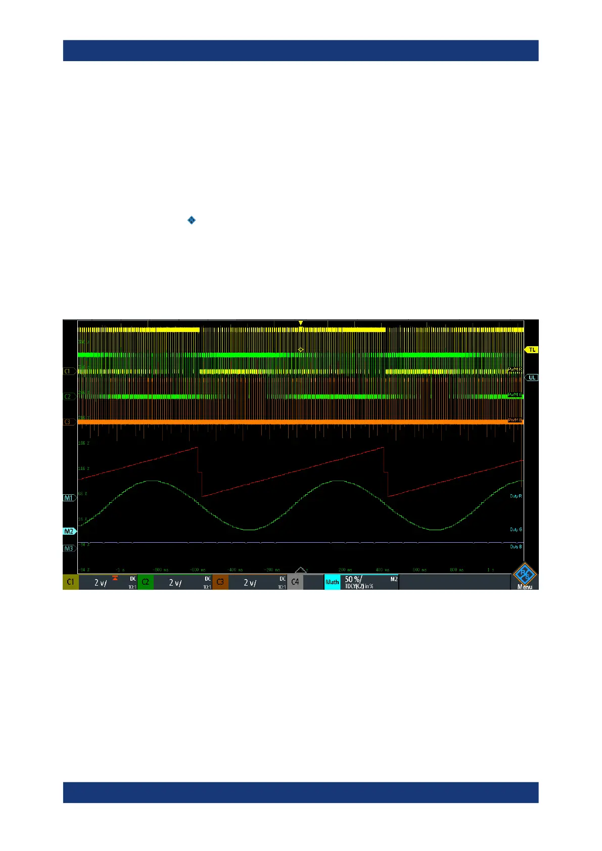
Figure 16-2: PWM test signals used for RGB LED control: P0 connected to C1, P1 to C2, and P2 to C3
► To configure the generated signal, you set:
a) "Output Voltage", see "Output Voltage" on page 414
b) "Frequency", see "Frequency" on page 414
c) Period, bit time and burst, see Chapter 16.2.4.3, "Timing setup", on page 418
d) Pattern trigger, see "Pattern trigger" on page 417
Pattern generator