Power analysis (option R&S RTM-K31)
R&S
®
RTM3000
367User Manual 1335.9090.02 ─ 09
e) Scroll down. Select "Power".
To adjust the probes, open the "Probe" menu. For details, see Chapter 14.1.2, "Probe
settings for power measurements", on page 344.
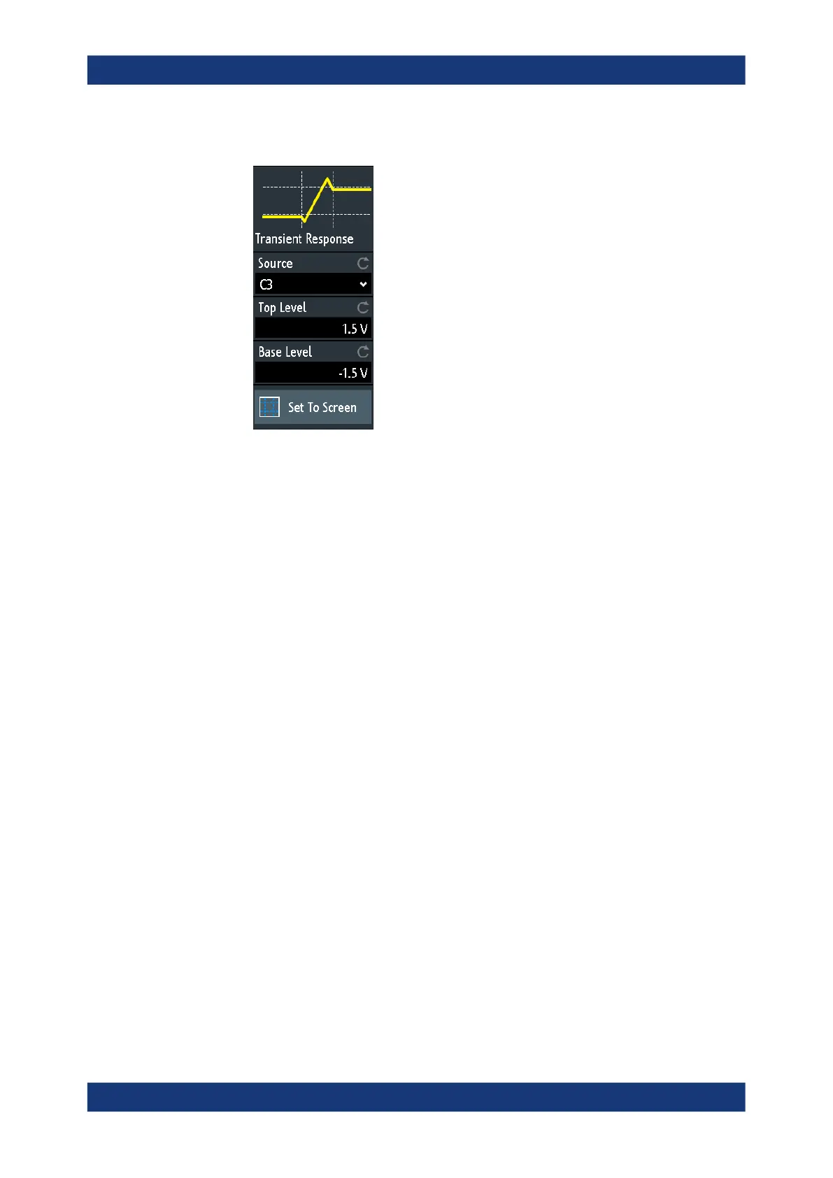
The settings for the sources is the same as for ripple analysis, see "Source"
on page 362.
Top Level
Sets the expected signal high voltage value.
Remote command:
POWer:TRANsient:SIGHigh on page 766
Base Level
Sets the expected signal low voltage value.
Remote command:
POWer:TRANsient:SIGLow on page 766
Set to Screen
Resets the cursors to their initial positions. This is helpful if the cursors have disap-
peared from the display or need to be moved for a larger distance.
14.6 Switching power measurements
Switching and control loop analysis is used to measure the internal characteristics of a
switching device and the operational reliability of the components.
● Slew rate............................................................................................................... 368
● Modulation.............................................................................................................370
● Dynamic on resistance..........................................................................................373
Switching power measurements