Serial bus analysis
R&S
®
RTM3000
330User Manual 1335.9090.02 ─ 09
Minimum/Maximum ← Data ← Cmd. and data
Opens the "Minimum"/"Maximum" submenu.
After setting the "Compare" condition, you can enter the value bit-by-bit by setting the
state high, low or do not care for each single bit. Alternatively, you can enter a hexa-
decimal value.
Remote command:
TRIGger:A:MILStd:DATA:MAXimum on page 683
TRIGger:A:MILStd:DATA:MINimum on page 683
13.8.4 MIL-STD-1553 decode results
When the configuration of the serial bus is complete, the signal can be decoded:
1. In the "Bus" menu, enable "Decode".
2. In the "Display" menu, select the result display settings.
See Chapter 13.1.2, "Displaying decode results", on page 253.
3. In the "Bus Table" menu, enable the "Bus Table". Adjust the table settings.
See also: Chapter 13.1.3, "Bus table: decode results", on page 254
The instrument captures and decodes the signal according to the protocol definition
and the configuration settings.
The color-coding of the various protocol sections and errors simplifies the interpretation
of the visual display. The decode information condenses or expands, depending on the
horizontal scale. Various data formats are available to show the result values.
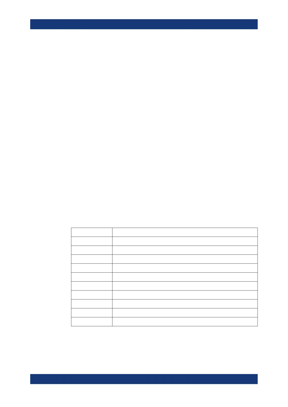
Table 13-7: Content of the MIL-STD-1553 frame table
Column Description
Start time Time of word start in relation to the trigger point
Type Word Type
RTA RT address
Label Symbolic label, available if a label list was loaded and applied
T/R Data direction, transmit or receive
Sub Subaddress
Length Number of data bytes
Data Hexadecimal values of the data bytes
RT/IMG Response time/intermessage gap time
State Overall state of the word
Remote commands are described in Chapter 17.11.8.3, "MIL-1553 decode results",
on page 689.
MIL-STD-1553 (option R&S
RTM-K6)