Getting started
R&S
®
RTM3000
31User Manual 1335.9090.02 ─ 09
The required ratings are listed next to the AC power connector and in the data
sheet.
3.2 Instrument tour
3.2.1 Front view
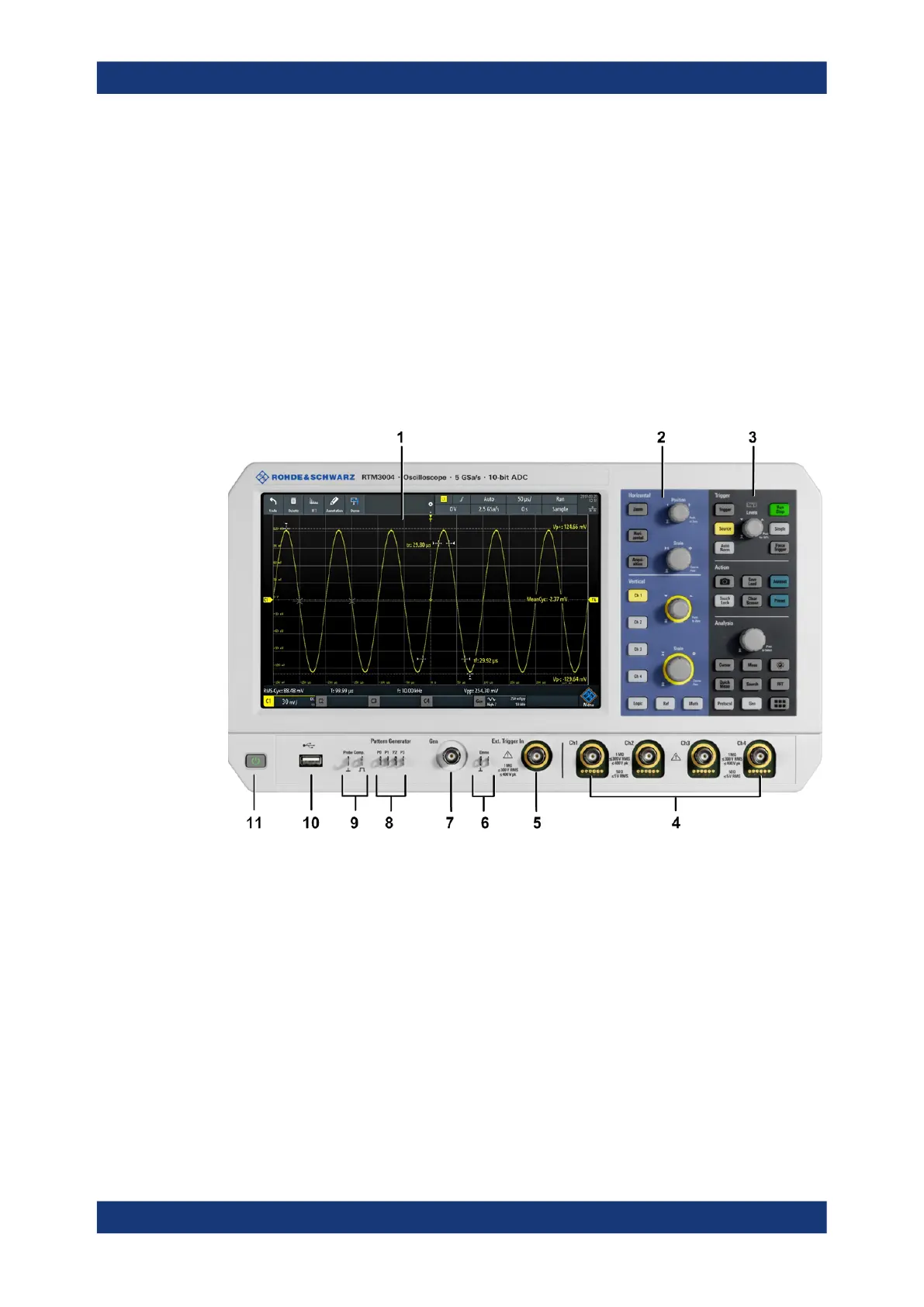
Figure 3-1 shows the front panel of the R&S RTM3000. The function keys are grouped
in functional blocks to the right of the display.
Figure 3-1: Front panel of R&S
RTM3000 with 4 input channels
1 = Display
2 = Horizontal and vertical setup controls
3 = Trigger settings, action and analysis controls
4 = Analog input channels (BNC)
5 = External trigger input
6 = Connectors for demo signal output
7 = Connector for optional function generator output (BNC, R&S RTM-B6)
8 = Connectors for optional pattern generator (R&S RTM-B6)
9 = Connectors for probe compensation
10 = USB connector
11 = [Standby] key
The R&S RTM3002 has 2 input channels, and the R&S RTM3004 has 4 input chan-
nels.
Instrument tour