Getting started
R&S
®
RTM3000
32User Manual 1335.9090.02 ─ 09
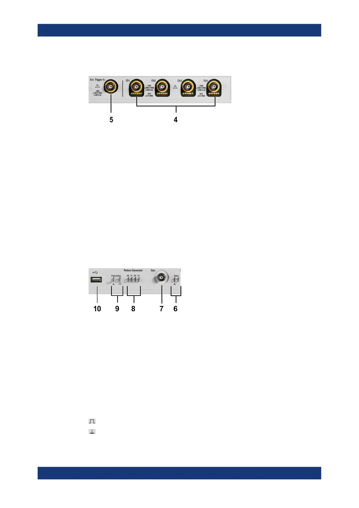
3.2.1.1 Input connectors
BNC inputs (4 and 5)
The R&S RTM3000 has two or four channel inputs (4) to connect the input signals. The
external trigger input (5) is used to control the measurement by an external signal. The
trigger level can be set from -5 V to 5 V.
For channel connectors, the input impedance is selectable, the values are 50 Ω and
1 MΩ.
The maximum input voltage is 400 V (peak), 300 V (RMS) at 1 MΩ input impedance
and 30 V (peak), 5 V (RMS) at 50 Ω input impedance.
For the external trigger input, the maximum input voltage is 400 V (peak) and
300 V (RMS) at 1 MΩ input impedance.
Transient overvoltages must not exceed 400 V (peak).
3.2.1.2 Other connectors on the front panel
[Demo] (6)
The pins are intended for demonstration purposes.
[Gen]: Function Generator (7)
BNC output of the function generator (with option R&S RTM-B6).
[Pattern Generator] (8)
Connectors for the pattern generator P0, P1, P2, P3.
[Probe Comp.] (9)
Probe compensation terminal to support adjustment of passive probes to the oscillo-
scope channel.
Square wave signal for probe compensation.
Ground connector for probes.
Instrument tour