boards.fm
P31003-H3560-S403-54-7620, 09/05
HiPath 3000 V6.0, HiPath 5000 V6.0, Provisional Service Manual
3-103
Boards for HiPath 3000
Peripheral Boards
LED statuses and their meanings
V.24 interface
The V.24 cable (C30267-Z355-A25) is used for connecting the service PC.
The following settings must be chosen for a terminal or PC connected to the V.24 interface:
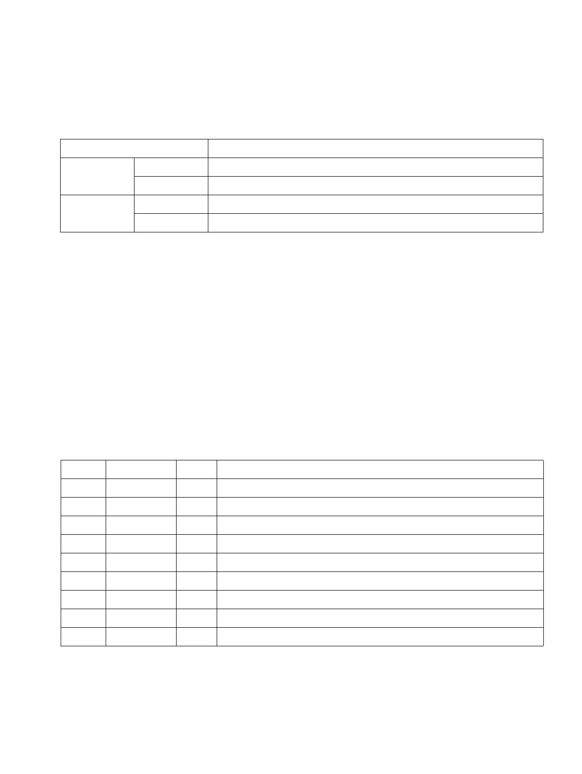
Table 3-39 HXGM3 - LED Concept
LED Meaning
H1 - green
Off Board is active but there are no active calls.
On At least one call is active.
H0 - red
On Error
Flashing Start (after a restart)
Transmission rate 19,200
Data bits 8
Parity bit None
Stop bits 1
Data flow control None
It is recommended that the local echo be deactivated on the connected terminal or PC.
Table 3-40 HXGM3 - Assignment of V.24 Interface X10
Pin Signal I/O Remark
1
2 RxD I Internal pull-up resistor in level switch (MAX211E)
3 TxD O
4DTRO
5 0 V Ground
6 DSR I Internal pull-up resistor in level switch (MAX211E)
7RTSO
8 CTS I Internal pull-up resistor in level switch (MAX211E)
9
 Loading...