Installing HiPath 3000
P31003-H3560-S403-54-7620, 09/05
4-148 HiPath 3000 V6.0, HiPath 5000 V6.0, Provisional Service Manual
inst_h3.fm
Installing HiPath 3750, HiPath 3700
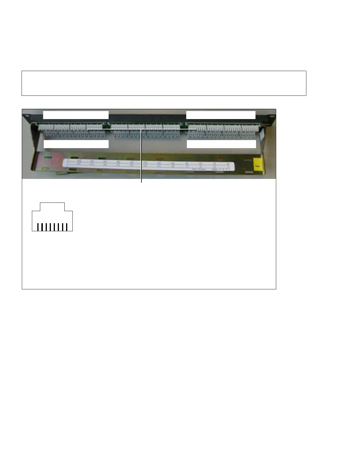
Structure of the S
0
patch panel C39104-Z7001-B3
CABLUs must be manually connected to the S
0
patch panel (Figure 4-84). You can use the Kro-
ne wiring tool for this.
Refer to the following tables for information on the assignment of the MW8 jacks:
● Table 3-107 for STMD8 board
● Table 3-173 for REAL board
>
All incoming cables must be attached to the patch panel using cable ties.
Figure 4-83 S
0
Patch Panel C39104-Z7001-B3
... 753123 21 19 17 ...
... 864224 22 20 18 ...
3x8MW8 jacks, numbering
81
:
Pin
MW8 jack assignment:
as a subscriber line as a trunk connection
3 Transmit + Receive +
4 Receive + Transmit +
5 Receive – Transmit –
6 Transmit – Receive –
Necessary height units for 19-inch cabinet assembly: 1
(one height unit corresponds to approx. 1.7’’=43 mm)
 Loading...