inst_h3.fm
P31003-H3560-S403-54-7620, 09/05
HiPath 3000 V6.0, HiPath 5000 V6.0, Provisional Service Manual
4-61
Installing HiPath 3000
Installing HiPath 3800
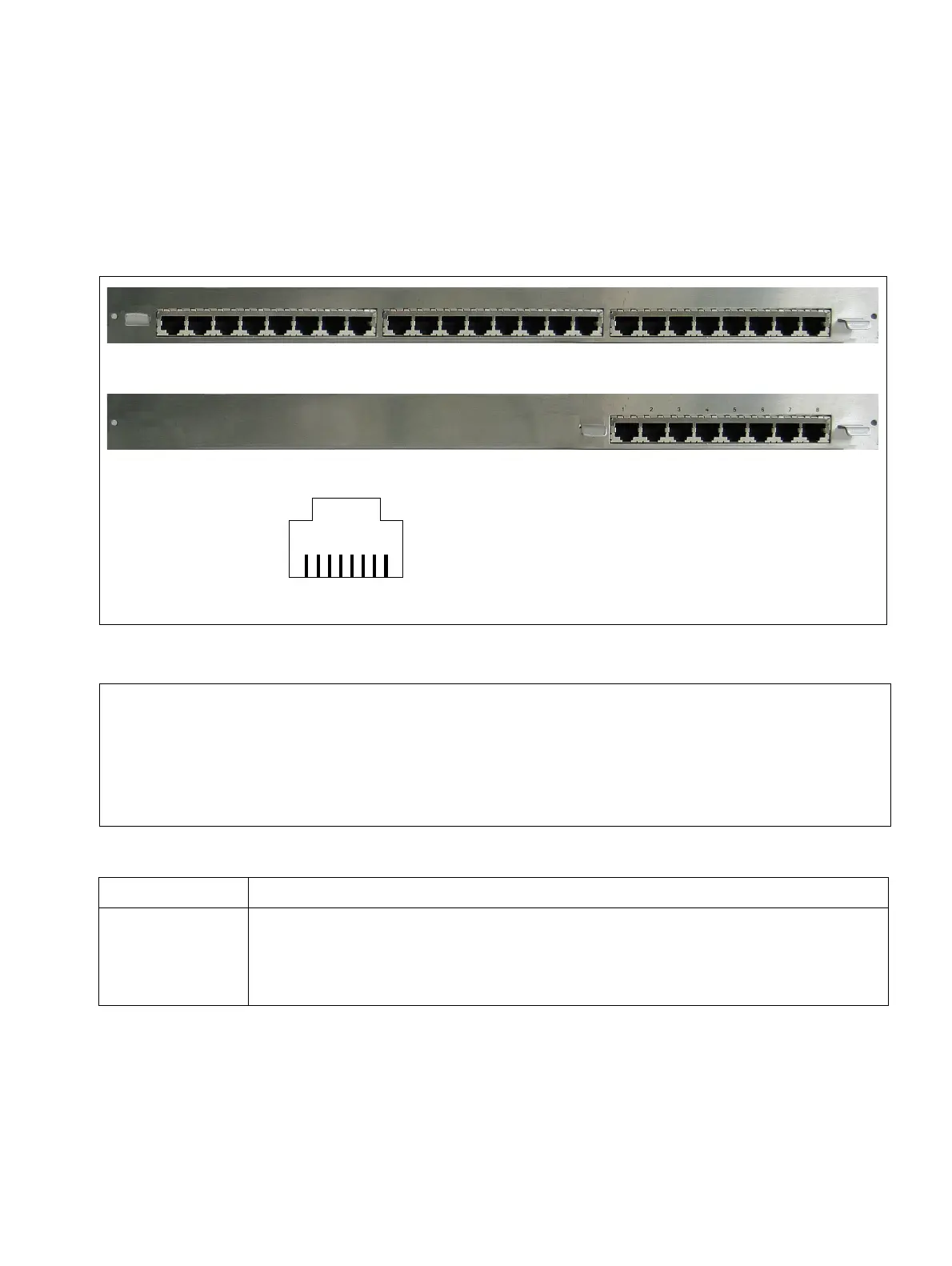
4.2.6.5 Connecting Peripherals to the Connector Panels with RJ45 Jacks
The boards should be installed in the cabinets as described in Section 4.2.5. The connector
panels plugged into the SIVAPAC connectors of the backplane are equipped with eight or 24
RJ45 jacks according to the relevant board.
Connect the peripheral directly to the 8-pin RJ45 jacks on the connector panels.
Figure 4-34 HiPath 3800 - connector panels with RJ45 Jacks
7
Danger
Be sure to connect the main protective earthing terminal on all system cabinets to
the grounding point of the electrical building installation before connecting up the pe-
ripherals (for example, potential equalization bus).
The system may only be started (connected to the power supply) if all system cabi-
nets are sealed at the rear with the connection and filler panels provided.
If Then
Slot with
STMD3
Connector panel with eight RJ45 jacks: S30807-Q6624-X
The RJ45 jacks are configured with four wires. S
0
stations can be directly
connected (1:1 cable). The receive and send lines should be switched for
trunk connections.
81
8-pin RJ45 jack
Connector panel with 24 RJ45 jacks
Connector panel with eight RJ45 jacks
 Loading...