R3765/67G Series Network Analyzer Operation Manual
7.10 Software Fixture Function (OPT 71/72)
7-106
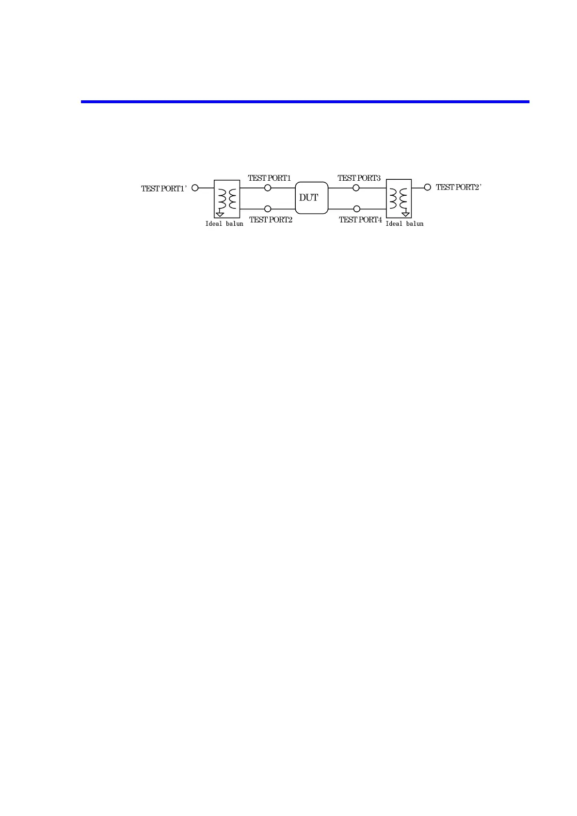
• When measuring a 4-port device (OPT 14 is required)
An ideal balun is connected between TEST PORT 1 and TEST PORT 2 and these ports are
converted into the balanced port TEST PORT 1’.
An ideal balun is connected between TEST PORT 3 and TEST PORT 4 and these ports are
converted into the balanced port TEST PORT 2’.
The DUT is measured as a 2-port network of TEST PORT 1’ to TEST PORT 2’ and S-
parameters are displayed as SS11, SS21, SS12 and SS22.
7.10.2.7 Mode Analysis Function (OPT 71 only)
The mode analysis function is used to measure the balanced device for each common mode and
differential mode components. The common mode component is a signal component generated
between the neutral point of the balanced port and GND. The differential mode component is a
signal component generated between the balanced ports.
Note: The mode analysis function is not available for OPT 72.
There are four kinds of mode analysis as shown below.
• Differential mode input and differential mode output: S-parameters are displayed as
Sdd11, Sdd21, Sdd12 and Sdd22.
• Differential mode input and common mode output: S-parameters are displayed as
Scd11, Scd21, Scd12 and Scd22.
• Common Mode input and differential mode output: S-parameters are displayed as
Sdc11, Sdc21, Sdc12 and Sdc22.
• Common Mode input and common mode output: S-parameters are displayed as
Scc11, Scc21, Scc12 and Scc22.
As for the subscripts of the S-parameter, an alphabet shows the mode and a number shows the
measurement port. Both alphabet and number subscripts are displayed in the order of output and
input in the same way as a generally used S-parameter.
Alphabet subscript d: Differential mode
c: Common mode
Number subscript 1: Shows TEST PORT 1 for a 3-port device and the balanced PORT 1
consisting of TEST PORT 1 and TEST PORT 2 for a 4-port device.
2: Shows the balanced PORT 3 consisting of TEST PORT 2 and TEST
PORT 3 for a 3-port device and the balanced PORT 2 consisting of
TEST PORT 3 and TEST PORT 4 for a 4-port device.
Example:
Sdc21 indicates the transmission characteristics of the DUT with the common mode input to
PORT 1 and differential mode output from PORT 2.
Sdc22 indicates the reflection characteristics of the DUT with the differential mode input to PORT
2 and common mode output from PORT 2.
 Loading...

