R3765/67G Series Network Analyzer Operation Manual
7.10 Software Fixture Function (OPT 71/72)
7-107
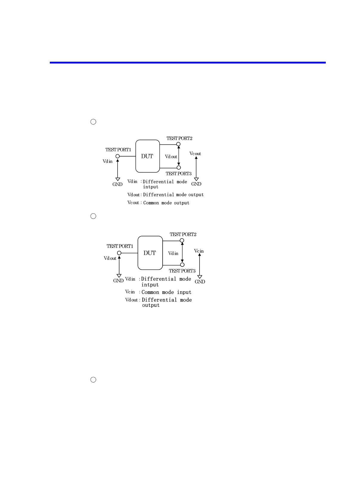
• When measuring a 3-port device (OPT 11 or 14 is required)
Since TEST PORT 1 is an unbalanced port, there is no distinction between common
mode and differential mode. However, TEST PORT 1 is measured as differential mode.
When the device is in forward direction (TEST PORT 1 is input and TEST PORT
2 and TEST PORT 3 are output)
When the device is in reverse direction (TEST PORT 1 is output and TEST PORT 2
and TEST PORT 3 are input)
• When measuring a 4-port device (OPT 14 is required)
When the device is in forward direction (TEST PORT 1 and TEST PORT 2 are
input, and TEST PORT 3 and TEST PORT 4 are output)
1
Differential mode→differential mode
Input reflection characteristics:
Sdd11
Differential mode→differential mode
Forward direction transmission
characteristics: Sdd21
Differential mode→common mode
Forward direction transmission
characteristics: Scd21
2
Differential mode→differential mode
Output reflection characteristics:
Sdd22
Differential mode→common mode
Output reflection characteristics:
Scd22
Common mode→common mode
Output reflection characteristics:
Scc22
Common mode→differential Mode
Output reflection characteristics:
Sdc22
Differential mode→differential mode
Reverse direction transmission
characteristics: Sdd12
Common mode→differential mode
Reverse direction transmission
characteristics: Sdc12
1
 Loading...

