IMAGE ACQUISITION
PRODUCT REFERENCE GUIDE
3
the sensor goes over a certain threshold, then a package is entering the image valid
start, and when it goes under the threshold, the package is providing the image valid
stop. In most cases this sensor is not sufficiently precise and an additional "Presence
Sensor" (AS1 or photoelectric sensor) input is used. An additional photoelectric sensor
or conveyor controller signal is usually connected to a separate trigger input.
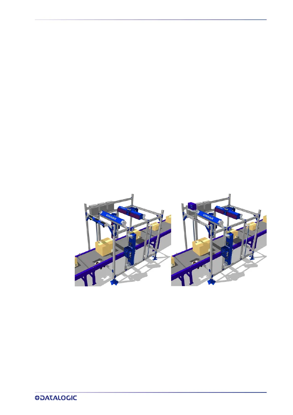
When the codes are located on more than one face of the parcel, more than one bar-
code reader-illuminator pair is necessary (multi-camera reading station). In this case,
one of the
barcode readers (the "Master") collects the information from all the sensors
and distributes it to the other barcode readers using a dedicated Ethernet connection.
A CBX connection box (CBX100, CBX510, CBX800) is
used to simplify the connection of
the camera to the other system components (photoelectric sensors, encoders, height
sensors, and etc.). There is only one CBX box in a multi headed system. This CBX box is
connected to the controller camera. Generally the CBX510 will be used. In cases where
Fieldbus is required the CBX800 will be needed.
A typical reading station will also include:
•
Power Supply Systems: The AV7000 requires a 24 Vdc power supply. Usually each
barcode reader-illuminator pair has its own power supply system (i. e. PWR-480B).
•
Connection Box: CBX100, CBX510, or CBX800
•
Height/Side Position Sensor: RangeFinder, DM3610, light curtain or S85
•
External Deflection Mirrors: To cover the requested reading field, the cameras
must be positioned at a given distance from their targets. In order to create read-
ing stations as small as possible, a deflection mirr
or is often inserted between the
target and the barcode reader.
Image Acquisition
Each barcode reader contains two distinct groups of devices:
• The acquisition device or "camera." This part of the AV7000 has to work in strict
r
eal time to acquire the best possible images.
• The decoding device or “decoder." This part of the AV7000 interprets the data
re
ceived through the camera.
The Standard AV7000 barcode reader contains both the camera and the decoder.
As already mentioned, the camera needs three kinds of external sensors:
•
Speed Sensor: At all times the camera needs to know the speed of the objects to
be acquired. The speed sensor is usually an encoder/tachometer connected to the