MECHANICAL INSTALLATION
28
AV7000 LINEAR CAMERA
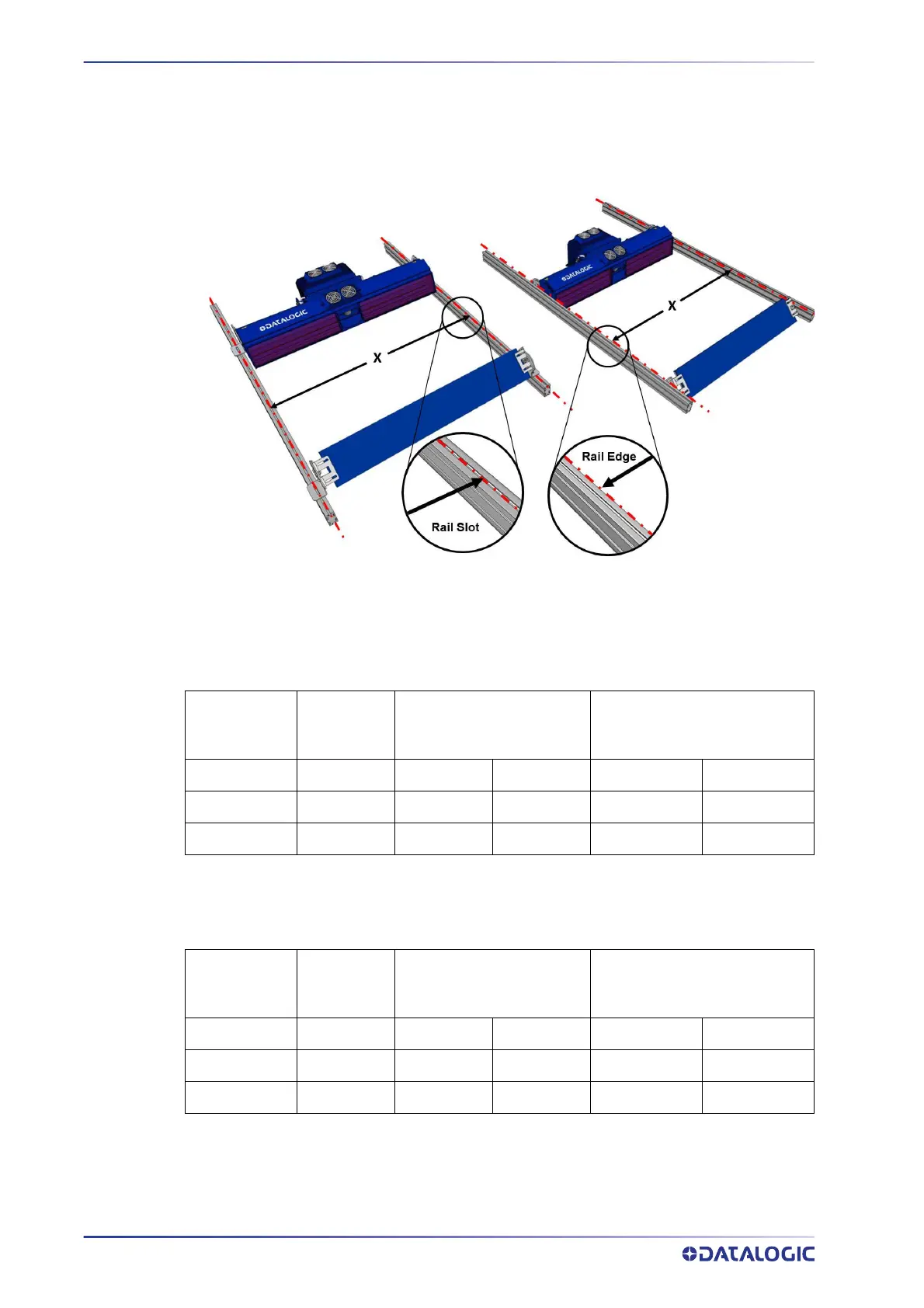
Mounting Rails
The Camera/Illuminator and Deflection Mirror are mounted to mounting structure rails,
as shown below. Typically, the rising brackets are mounted to the rails, but in some
cases it may be necessary to mount the camera and deflection mirror between the
mounting rails.
For Rail configurations, the rails must be mounted so that the distance between the
extrusion profiles (Bosch or 80/20) matches the illuminator model being used.
For Top Camera positions (both Direct and Indirect), the distance between the profiles
m
easured from the internal sides is given in the following table depending on the illumi-
nator model:
Illuminator
Body
Width
x Distance Between Rail
Slo
ts with Rising
Brackets
x Distance Between Rails
without Rising Brackets
Short
845 mm 945 mm 37.2 in 885 mm 34.8 in
Medium
1150 mm 1250 mm 49.2 in 1190 mm 46.8 in
Long
1480 mm 1580 mm 62.2 in 1520 mm 59.8 in
For Side Camera positions (either Direct or Indirect), the distance between the profiles
measured from the internal sides is given in the following table depending on the illumi-
nator model:
Illuminator
Body
Wid
th
x Distance Between Rail
Slo
ts with Rising
Brackets
x Distance Between Rails
without Rising Brackets
Short
845 mm 955 mm 37.6 in 895 mm 35.24 in
Medium
1150 mm 1260 mm 49.6 in 1200 mm 47.24 in
Long
1480 mm 1590 mm 62.6 in 1530 mm 60.24 in