CBX100
PRODUCT REFERENCE GUIDE
71
CBX100
Please verify that the CBX100 connection box is configured for the AV7000 application
as follows:
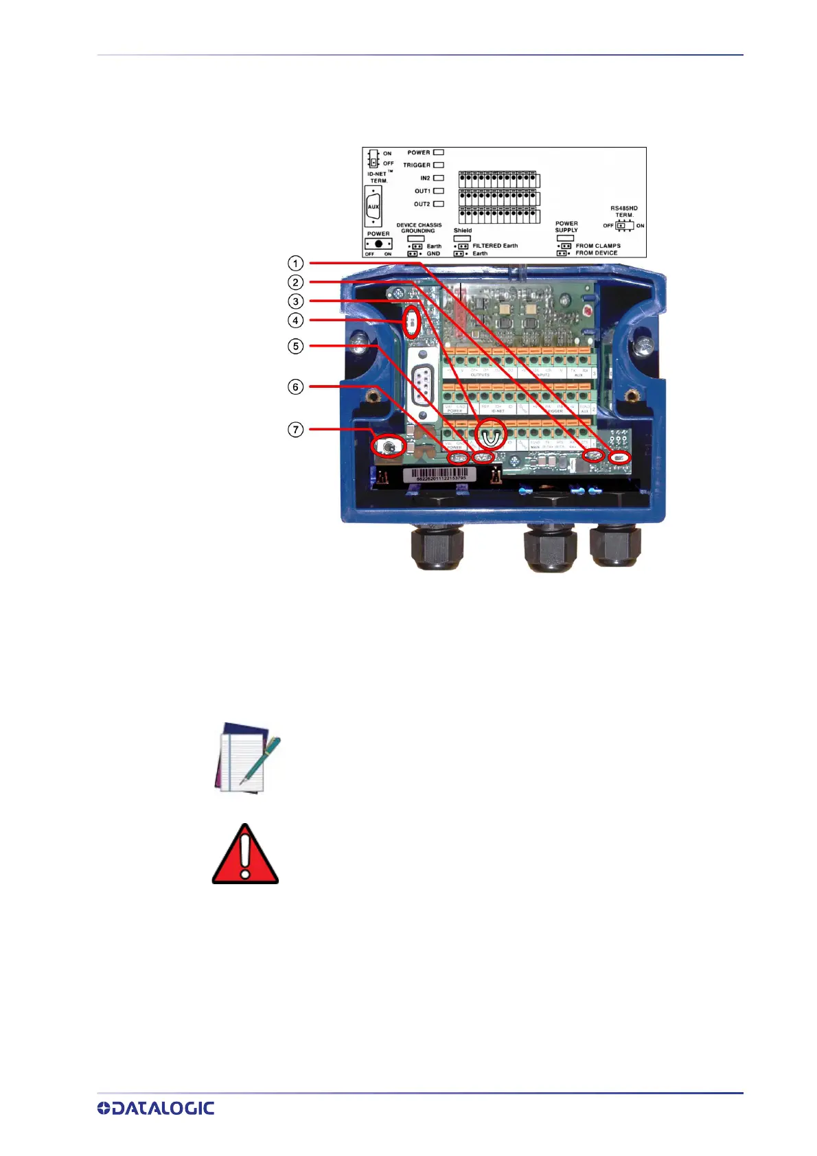
Reference the image and diagram above:
1. Set RS422HD TERM switch to OFF.
2. Set POWER SUPPLY jumper to FROM DEVICE.
3. Insert jumper wire in pin block from REF to ID+ (one jumper in either block is suffi-
cient).
4. Set ID-NET TERM switch to OFF.
5. Set Shield jumper to FILTERED Earth.
6. Set DEVICE CHASSIS GROUNDING to Earth.
7. Set POWER Switch to ON.
NOTE: In order for a standalone or Master AV7000 to initialize properly, it
must be connec
ted to a CBX100. On power-up the AV7000 looks for the
jumper (item number 3 in the image above) and will assume the responsi-
bility of provided the SYNC Network IP addresses. Slave units in an array/
tunnel will receive their SYNC Network IP addresses from the Master.
WARNING: Although multiple AV7000 cameras can have a CBX box, only
one
of the CBX boxes in a multi-camera system can have the jumper to
make it the Master.