ELECTRICAL INSTALLATION
60
AV7000 LINEAR CAMERA
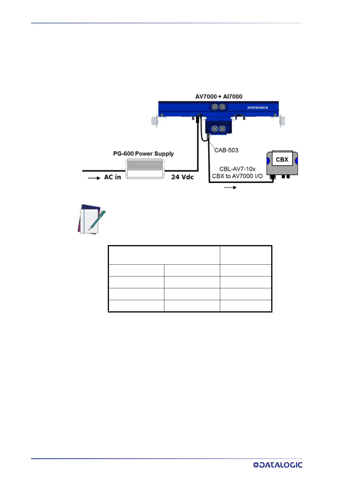
The CBX510 connection box receives power through the CBL-AV7-10x from the AV7000
IO connector.
A PWR-480B is able to power:
One AI7000 illuminator (including the AV7000 c
amera which is powered via this unit
and one CBX510 with all the standard sensors)
The power supply unit is connected to the camera illuminator according to the following
d
iagram (power supply side):
CVL-2389 Wire Color or Number (Depend-
ing on Source)
Function
White 1 GND
Green 2 + 24 Vdc
Red 3 + 24 Vdc
Black 4 GND
The CBX510 connection box receives power through the CBL-AV7-10x from the AV7000
IO connector.
NOTE: The AI7000 series illuminators are supplied with CVL
-2389 exten-
sion power cable. Use this cable to connect the PWR-480B power supply by
cutting off the cable’s male Amphenol connector and connecting the wires
to the PWR-480B according to the table below: