440 01-6203-01R3, CG Drives & Automation
The status signals can be assigned to digital outputs.
Configuration of digital outputs
429
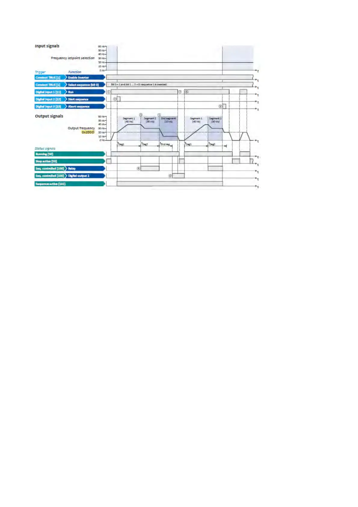
① If the inverter is enabled and no error is active, the motor can be started with the
"Run" function.
As the sequence has not been started yet, first the normal setpoint control is
active.
② The "Start sequence" function is used to start the selected sequence in an edge-
controlled way.
③ Sequencer mode 0x4025 (P800.00) = "Time operation [1]":
The switch-over to the next step of the sequence is made after the time set for the
current segment has elapsed.
④ The segment 2 is configured here in such a way that the relay will be triggered
during the time of processing.
⑤ End of sequence mode 0x402F (P824.00) = "Keep running [0]":
After the sequence has been processed, the setpoint set for the end segment is
continuously transmitted to the motor control until the sequence is aborted.
⑥ In case of the end segment, the time setting determines the delay after which the
configured output states are to become active. Here, the end segment is
configured in such a way that the digital output 1 is set after 10 s have expired.
⑦ If the "Run" function is set to FALSE, the motor is stopped with the stop method set
in 0x2838:003 (P203.03). The started sequence, however, remains active and the
sequencer-controlled outputs keep their state.
⑧ Start of sequence mode 0x4040 (P820.00) = "Restart sequencer [0]":
If the "Run" function is set to TRUE again, the (still active) sequence is restarted.
⑨ The "Abort sequence" function is used to abort the sequence in an edge-controlled
way.
In this case, the standard setpoint or the setpoint source selected via setpoint
change-over is active again.