Example for operating mode
In the following example, the digital inputs 2 and 3 are used for controlling the sequencer.
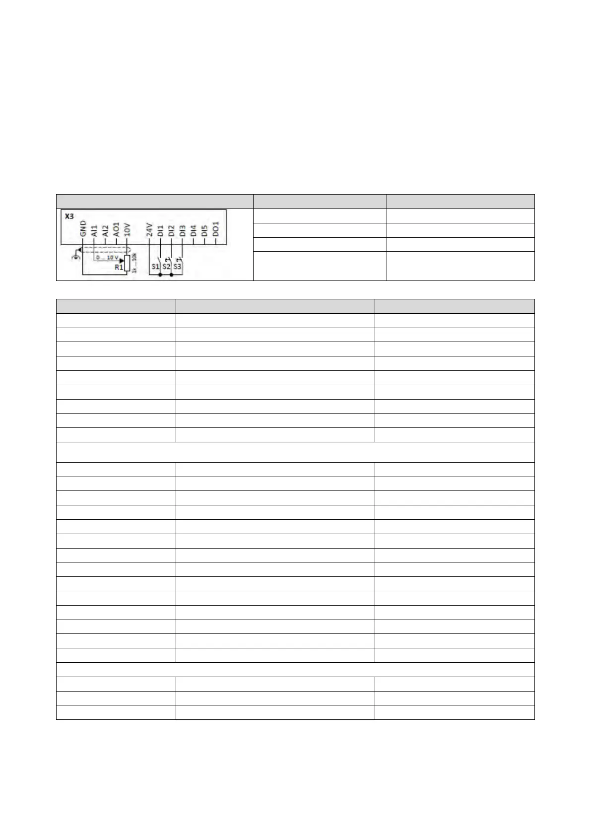
• The analog input 1 is set as standard setpoint source.
• Switch S1 starts the motor in forward direction of rotation. Switch S1 in the initial
position stops the motor again.
• Button S2 starts the sequence, button S3 aborts the sequence. After the abortion, the
normal setpoint control is active again.
0x2631:013 (P400.13)
Invert rotation
Not connected [0]
Sequencer controlled [100]
0x2634:002 (P420.02)
Digital output 1
Sequencer controlled [100]
Segment and sequence configuration
In this example, only the sequence 1 is used. The sequence consists of two steps (segment 1 and segment 2).
Sequencer segment 1: Frequency setpoint
0x4026:002 (P801.02)
Sequencer segment 1: Acceleration/deceleration
20 s
Sequencer segment 1: Time
Sequencer segment 1: Digital outputs
Sequencer segment 2: Frequency setpoint
Sequencer segment 2: Acceleration/deceleration
0x4027:003 (P802.03)
Sequencer segment 2: Time
14 s
Sequencer segment 2: Digital outputs
End segment: Frequency setpoint
End segment: Acceleration/deceleration
0x402E:004 (P822.04)
End segment: Digital outputs
0x04 (only digital output 1)
0x402F (P824.00)
End of sequence mode
Keep running [0]