214323 106 Revision A
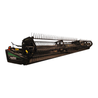
Figure 3.129: AHHC Sensor Assembly for Use
with CLAAS Combines
1. Complete the following steps to adjust high
voltage limit:
a. Extend guard angle fully; header angle indicator
should be at D.
b. Position header 152–254 mm (6–10 in.) above
ground; float indicator should be at 0.
c. Loosen sensor mounting bolts (A).
d. Slide sensor support (B) to right to increase high
voltage limit or to left to decrease it.
e. Tighten sensor mounting bolts (A).
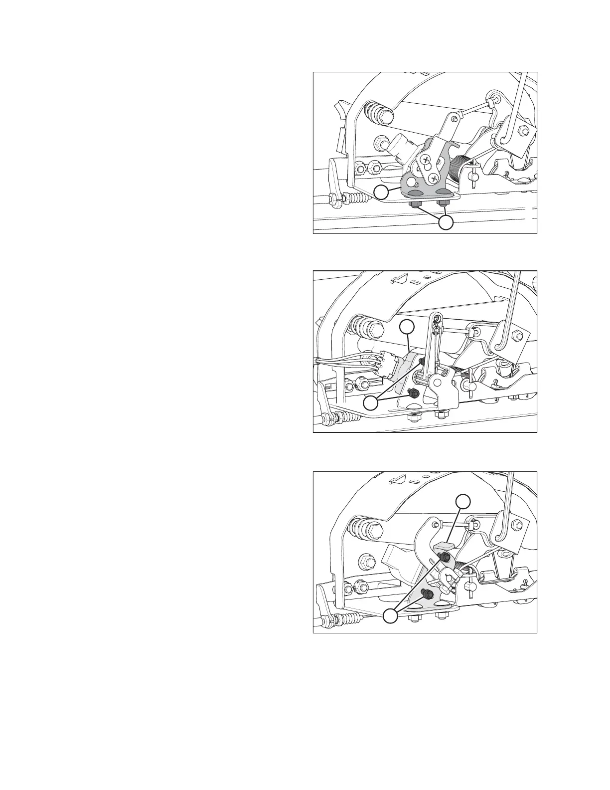
Figure 3.130: Most Common 5 Volt AHHC
Sensor Assembly
2. Complete the following steps to adjust low voltage limit:
a. Extend guard angle fully; header angle indicator
should be at D.
b. Fully lower header on ground; float indicator should
be at 4.
c. Loosen mounting bolts (A).
d. Rotate sensor (B) clockwise to increase low
voltage limit, or counterclockwise to decrease it.
e. Tighten sensor mounting bolts (A).
Figure 3.131: 10 Volt AHHC Sensor Assembly
for Use with Some New Holland Combines
OPERATION