214323 406 Revision A
3. Ensure the draper guide (rubber track on the underside of the draper) is properly engaged in the groove of the
drive roller and the idler roller is between the guides.
102234110223411022341
A
B
C
D
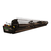
Figure 5.157: Feed Draper Tensioner (Spring
Box Drawn Transparent)
NOTE:
The default position of spring retainer (A) is flush to the
edge of spring box (B); however, the position of the
spring retainer varies with draper tracking adjustment at
the factory. Illustration shows transparent spring box to
show spring retainer position.
4. Check the position of spring retainer (A). If feed draper
tracks properly and spring retainers on both sides are
positioned within the following dimensions, than no
adjustment is necessary:
• Loosened to 3 mm (1/8 in.) outside (C) the front
edge of spring box (B)
• Tightened to 6 mm (1/4 in.) inside (D) the front edge
of the spring box (B)
5. If adjustment is necessary, proceed to Step 6, page 406.
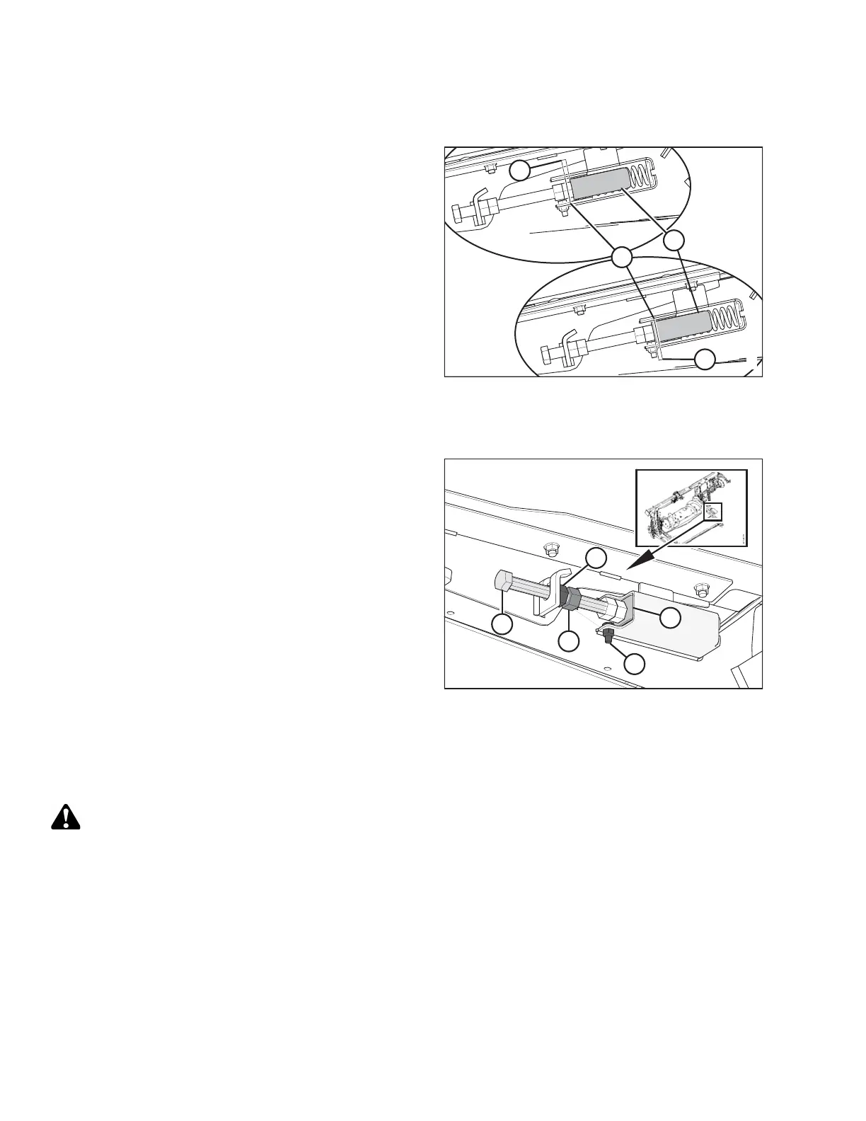
Figure 5.158: Tensioner
6. To adjust feed draper tension, loosen jam nut (A) and
hold nut (B) with a wrench while turning bolt (C)
clockwise to increase draper tension or
counterclockwise to decrease draper tension.
IMPORTANT:
To avoid uneven draper tracking, adjust both sides
equally.
7. Tension the draper until the spring retainer (D) is within
range described in Step 4, page 406, and bolt (E)
is free.
8. Tighten jam nut (A).
5.10.3 Adapter Drive Roller
Removing CA25 Feed Draper Drive Roller
DANGER
To avoid bodily injury or death from unexpected start-up or fall of a raised machine, always stop engine
and remove key before leaving the operator’s seat, and always engage safety props before going under
the machine for any reason.
1. If attached to the combine, detach the header from the adapter. Refer to 4.7.1 Detaching Header from Adapter
and Combine, page 310.
2. Raise the feeder house to its full height, stop the engine, and the remove key from the ignition.
3. Engage the combine safety props.
MAINTENANCE AND SERVICING