214323 58 Revision A
• Adjusting Stabilizer Wheels, page 55
• Adjusting Stabilizer/Slow Speed Transport Wheels, page 54
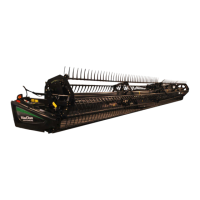
Figure 3.32: Outer Skid Shoe
3. Remove lynch pin (A) from each skid shoe (B).
4. Hold shoe (B) and remove adjustment pin (C) by
disengaging from the frame and pulling away from
the shoe.
5. Raise or lower skid shoe (B) to achieve the desired
position using the holes in the support as a guide.
6. Reinstall pin (C), engage in frame, and secure with
lynch pin (A).
7. Check that all skid shoes are equally adjusted.
8. Check the header float. Refer to 3.7.2 Header Float,
page 58.
3.7.2 Header Float
The header float system reduces the ground pressure at the cutterbar, allowing the header to more easily follow the
ground and quickly respond to sudden ground contour changes or obstacles.
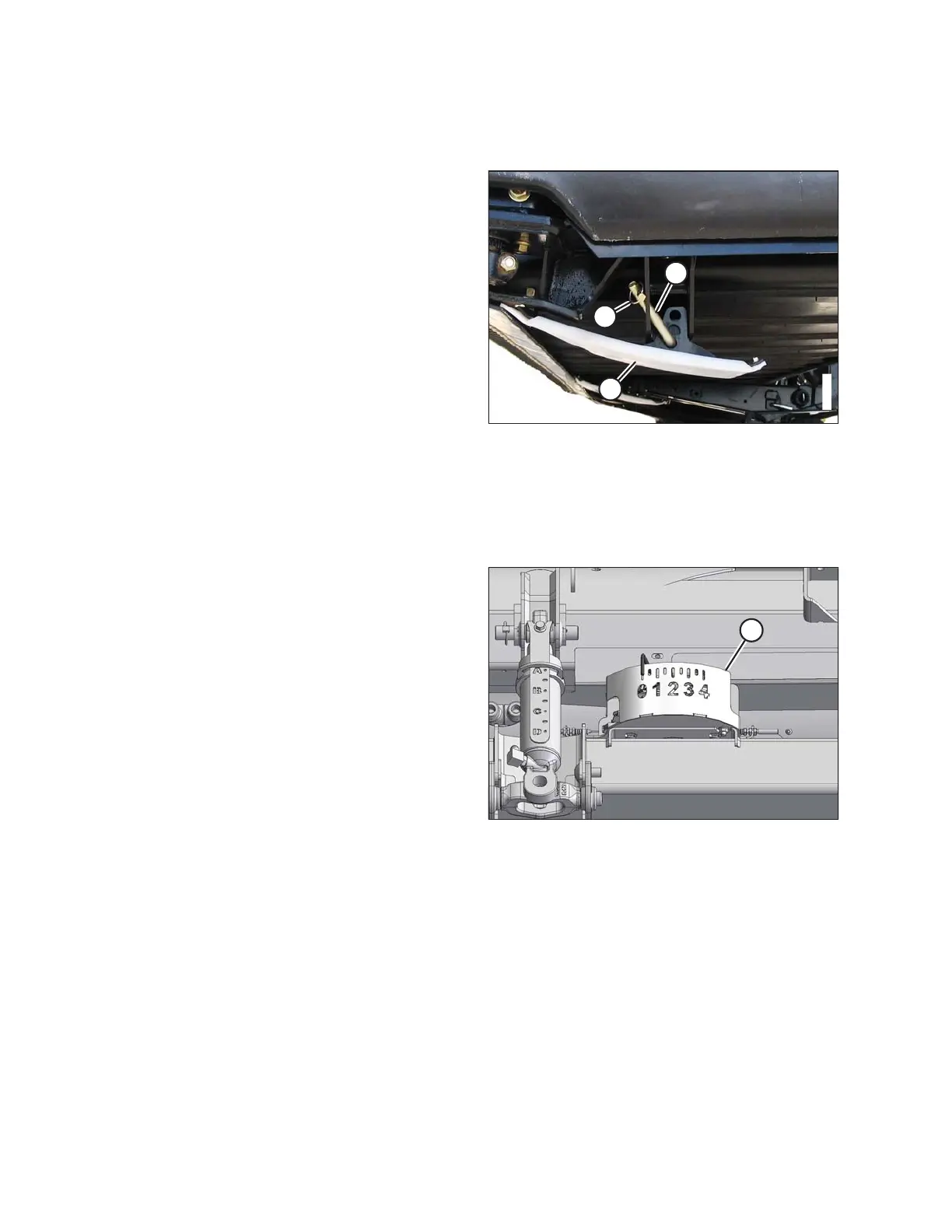
Figure 3.33: Float Indicator
Header float is indicated on the CA25 float indicator (A).
The values 0 to 4 represent the force of the cutterbar on the
ground with 0 being the minimum and 4 being
the maximum.
The maximum force is determined by the tension on the
adapter’s adjustable float springs. The tension is factory-
set, but it can be changed to suit field and crop conditions.
Refer to Checking and Adjusting Header Float, page 59.
OPERATION