214323 216 Revision A
Adjusting Voltage Limits
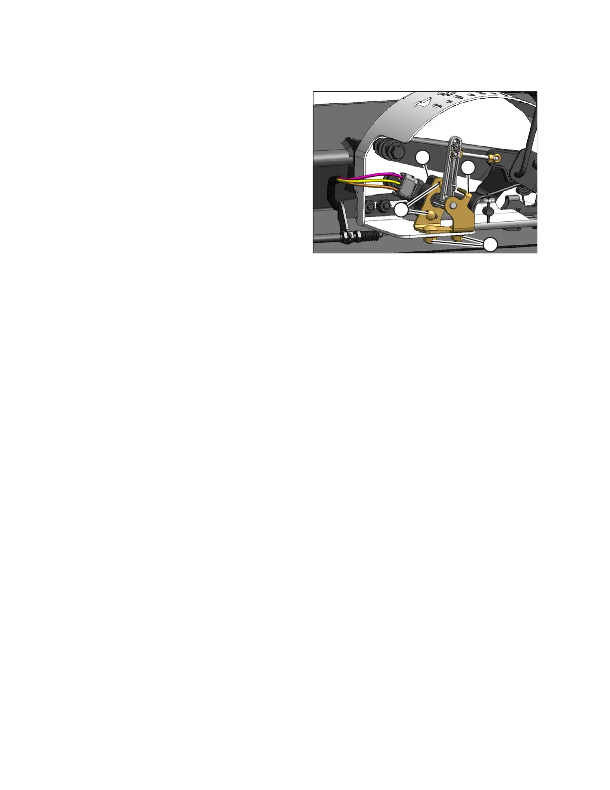
Figure 3.371: AHHC Sensor Assembly
1. To adjust high voltage limit:
a. Extend guard angle fully. Header angle indicator
should be at D.
b. Position header 150–254 mm (6–10 in.) above
ground. Float indicator should be at 0.
c. Loosen sensor mounting bolts (A).
d. Slide sensor support (B) to right to increase high
voltage limit, or to left to decrease it.
e. Tighten sensor mounting bolts (A).
2. To adjust low voltage limit:
a. Fully extend center-link, (i.e., increase header/
guard angle to maximum). Header angle indicator
should be at D.
b. Fully lower header to ground. Float indicator should
be at 4.
c. Loosen potentiometer mounting bolts (C).
d. Rotate potentiometer (D) clockwise to increase low
voltage limit, or counterclockwise to decrease it.
e. Tighten potentiometer mounting bolts (C).
3. When readings are in proper range, auto header height
control can be calibrated.
Calibrating Auto Header Height Control (CLAAS 700 Series)
The calibration procedure determines limits of auto header height sensor.
Calibrate auto header height system after initial header installation, and after replacing or adjusting any component
of auto header height system. If system does not function, calibrate it again.
For best performance of the auto header height control (AHHC), perform these procedures with center-link set to D.
When setup and calibration are complete, adjust center-link back to desired header angle. Refer to 3.7.4 Header
Angle, page 76.
NOTE:
Changes may have been made to combine controls or display since this document was published. Refer to
combine operator’s manual for updates.
1. Ensure center-link is set to D.
2. Ensure that header float is unlocked.
OPERATION