214323 113 Revision A
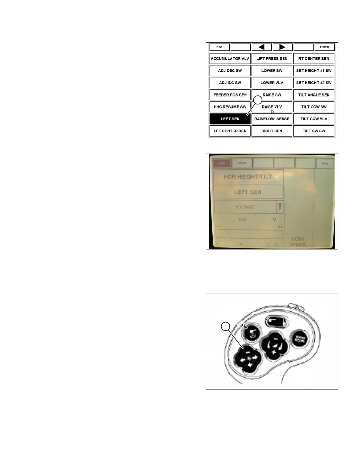
Figure 3.146: Case 8010 Combine Display
8. Select LEFT SEN (A). The exact voltage is displayed.
Raise and lower header to see full range of voltage
readings.
Figure 3.147: Case 8010 Combine Display
9. Adjust voltage limits (refer to Adjusting Voltage Limits,
page 105) if sensor voltage is not within low and high
limits, or if range between low and high limits is
insufficient (refer to Table 3.13, page 103).
Setting Header Controls (Case 8010)
The following procedure applies to Case 8010 combines without a shift button on the GSL.
Figure 3.148: Case Combine Controls
The reel fore/aft controls (A) also control header fore/aft tilt
(if header is equipped with the fore/aft tilt option). The
ground speed lever (GSL) needs to be configured to allow
the Operator to swap between reel fore/aft and header
fore/aft tilt.
OPERATION