214323 165 Revision A
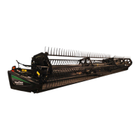
Figure 3.255: Hydrostatic Lever
2. Once HEADER HEIGHT RESUME and AUTO
HEADER CONTROL are turned ON, use buttons 2 (B)
and 3 (C) on your hydrostatic lever for active
header control.
NOTE:
Button 1 (A) is reserved for AUTO HEIGHT RESUME
which will return header to a certain height, but will not
automatically compensate for ground variation.
NOTE:
To use buttons, combine must be running, AUTO
HEADER HEIGHT SENSING must be ON, and header
switch and feeder house must be engaged.
3. Push button you would like to use, and header will
position itself at default height.
Figure 3.256: Auto Header Control Dial
4. Adjust header to desired ground pressure by turning
your auto header control dial located at upper right
corner of console (A). Once you have set your desired
ground pressure, auto header height will now maintain
constant float at this ground pressure (it will lower or
raise feeder house to compensate for changes in
ground height).
NOTE:
Auto header height is designed to optimize your float
when cutting on ground. It does not function when
cutterbar is off ground.
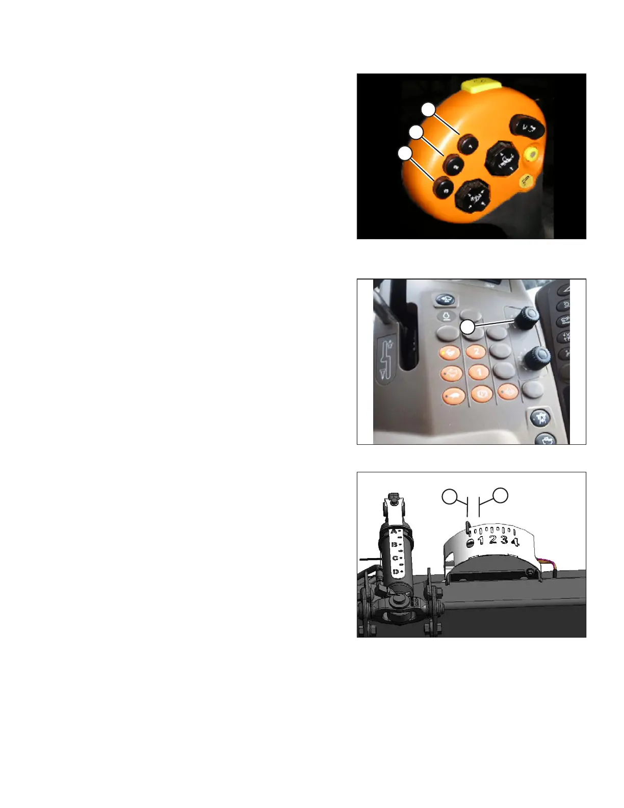
Figure 3.257: Float Indicator Box
NOTE:
The ideal ground pressure, in most cases, is one number
of separation on AHHC from having header fully
suspended off ground (B) to just resting on ground (A).
Operating with heavier pressures can wear cutterbar
wearplate prematurely.
5. The additional buttons (2 or 3) on hydrostatic lever are
used for two different ground pressure settings. The
header control dial on console will work for specific
button that was pushed to activate auto header height
control. Each time button is pushed, header will return
to that specific ground pressure.
3.8.9 John Deere 60 Series Combines
Checking Voltage Range from Combine Cab (John Deere 60 Series)
The auto header height sensor output must be within a specific range, or feature will not work properly.
OPERATION