214323 473 Revision A
Figure 5.307: Electrical Harness
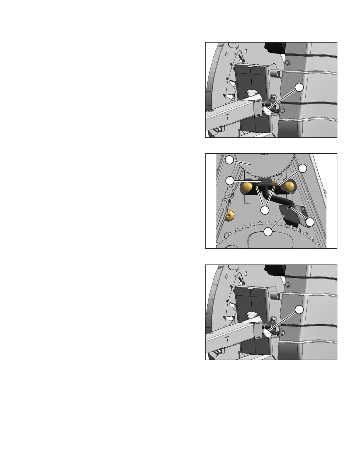
3. Disconnect electrical connector (A).
Figure 5.308: Speed Sensor
4. Cut cable tie (A) securing the harness to the cover.
5. Remove two screws (B) and remove sensor (C) and
harness. Bend cover (D) (if necessary) to remove the
harness.
6. Feed the wire of the new sensor behind cover (D) and
through the chain case.
7. Locate the new sensor in support (E) and attach with
two screws (B).
8. Adjust the gap between sensor disc (F) and sensor (C)
to 0.5 mm (0.02 in.).
Figure 5.309: Electrical Harness
9. Connect electrical harness (A).
IMPORTANT:
Ensure the sensor electrical harness does NOT contact
the chain or sprocket.
10. Reinstall the drive cover. Refer to Installing Reel Drive
Cover, page 462.
MAINTENANCE AND SERVICING