215916 181 Revision A
Figure 4.151: Header Support
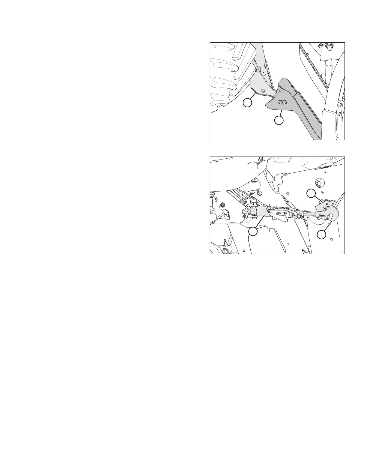
11. Drive the windrower slowly forward until feet (A) enter
supports (B). Continue to drive slowly forward until the feet
engage the supports and the header is nudged forward.
12. Ensure that feet (A) are properly engaged in supports (B).
Figure 4.152: Hydraulic Center-Link
13. Windrowers equipped with the self-aligning
center-link kit:
a. Adjust the position of center-link cylinder (A) with the
switches on the GSL until hook (B) is above the header
attachment pin.
IMPORTANT:
Hook release (C) must be down to enable the self-
locking mechanism to function.
b. If hook release (C) is open (in the up position), shut
down the engine, and remove the key from the
ignition. Manually push hook release (C) down after
the hook engages the header pin.
c. Lower center-link (A) onto the header with the REEL
DOWN switch on the GSL until the center-link locks into
position and hook release (C) is down.
d. Check that the center-link is locked onto the header by
pressing the REEL UP switch on the GSL.
OPERATION