215916 213 Revision A
14. If necessary, calibrate both the knife drive and header position sensors on the windrower. Calibrate both the knife
drive and header position sensors whenever you are:
• Attaching the header to the windrower for the first time
• Changing the speed sensor or hydraulic drive motor on the header
• Changing the header drive pump associated with the knife drive, Harvest Performance Tracker (HPT), or the master
controller on the windrower
For instructions, refer to .
Connecting R2 Series Rotary Disc Header Hydraulics and Electrical to Windrower
The procedure for connecting the R216’s hydraulic and electrical systems to the windrower differs depending on the
configuration of the windrower.
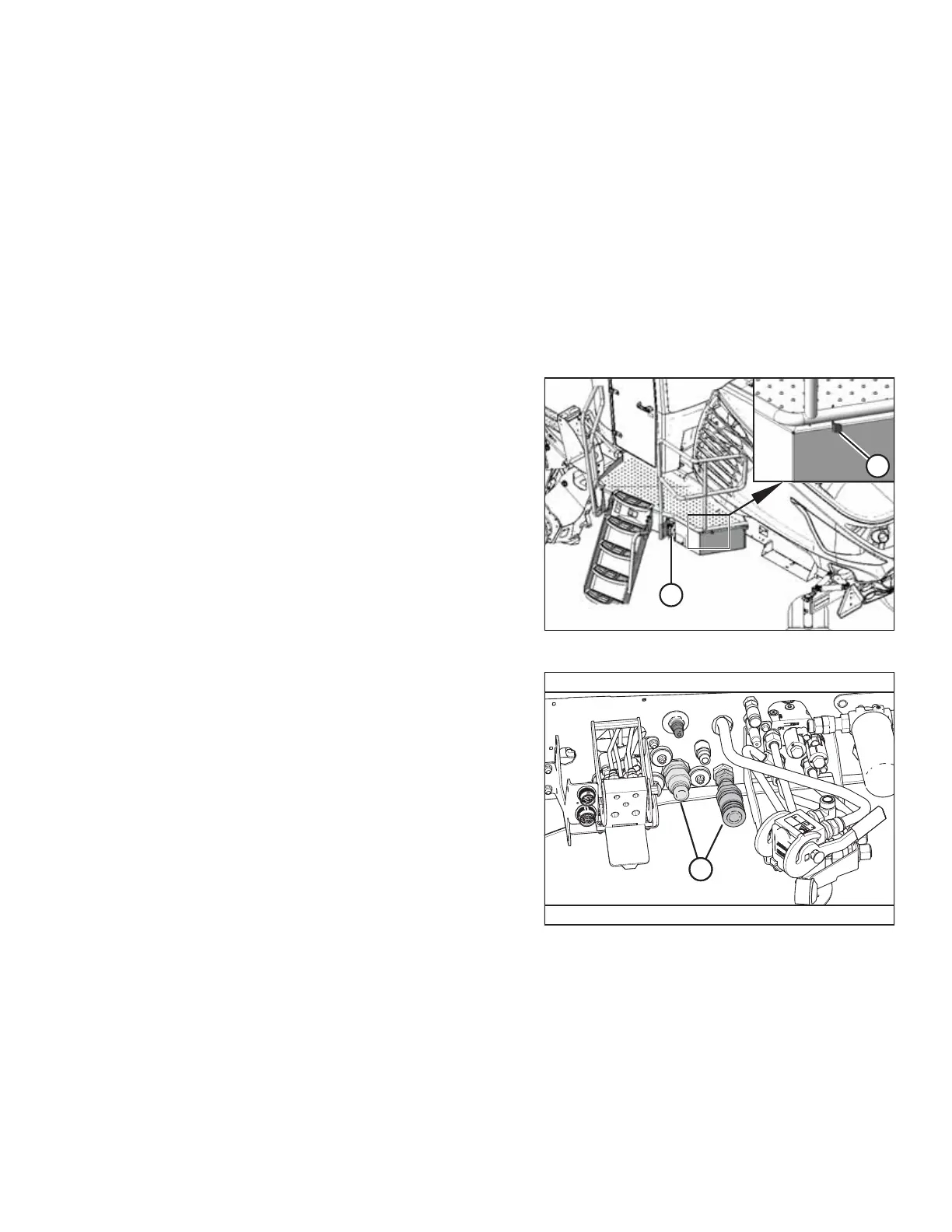
Figure 4.229: Left Cab-Forward Platform
1. Approach platform (A) on the left cab-forward side of the
windrower and ensure the cab door is closed.
2. Push latch (B), and pull platform (A) toward the walking
beam until it stops and the latch engages.
Figure 4.230: Header Hydraulics Configurations –
Auger/Rotary Disc/Draper-Ready
Proceed with the steps relevant to your windrower
configuration:
• Auger/rotary disc/draper-ready configuration (A): For
instructions, refer to Auger/Rotary Disc/Draper-Ready
Configuration – Quick Coupler Connections, page 214.
OPERATION