215916 196 Revision A
8. If necessary, calibrate both the knife drive and header position sensors on the windrower. Calibrate both the knife
drive and header position sensors whenever you are:
• Attaching the header to the windrower for the first time
• Changing the speed sensor or hydraulic drive motor on the header
• Changing the header drive pump associated with the knife drive, Harvest Performance Tracker (HPT), or the master
controller on the windrower
For instructions, refer to .
Detaching R1 Series Rotary Disc Header
Detaching an R1 Series header from an M1 Series windrower requires removing the electrical and hydraulic connections,
detaching the header supports, and releasing the center link.
DANGER
To prevent bodily injury or death from the unexpected startup of the machine, always stop the engine and remove the
key from the ignition before leaving the operator’s seat for any reason.
DANGER
Ensure that all bystanders have cleared the area.
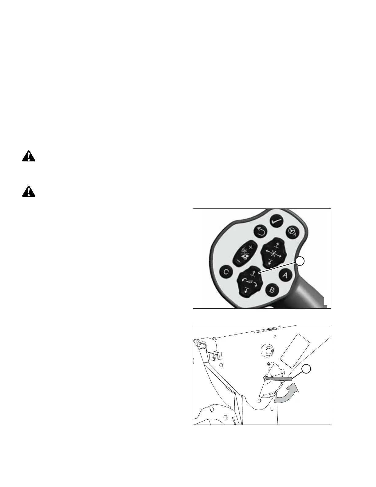
Figure 4.186: GSL
1. Start the engine.
2. Press switch (A) to raise the header to its maximum height.
3. Shut down the engine, and remove the key from
the ignition.
Figure 4.187: Safety Prop Lever
4. Engage the safety props on both lift cylinders as follows:
a. Pull lever (A) toward you to release it, and then rotate
it toward the header to lower the safety prop onto the
cylinder.
b. Repeat the previous step for the opposite lift cylinder.
IMPORTANT:
Ensure that the safety props engage over the cylinder piston
rods. If the safety prop does NOT engage properly, raise the
header until the safety prop fits over the rod.
OPERATION