215916 218 Revision A
Figure 4.241: Left Cab-Forward Platform
12. Pull platform (A) towards the cab until it stops and the latch
is engaged.
13. If necessary, calibrate both the knife drive and header position sensors on the windrower. Calibrate both the knife
drive and header position sensors whenever you are:
• Attaching the header to the windrower for the first time
• Changing the speed sensor or hydraulic drive motor on the header
• Changing the header drive pump associated with the knife drive, Harvest Performance Tracker (HPT), or the master
controller on the windrower
For instructions, refer to .
Rotary Disc Only Configuration – Hard-Plumbed Connections
The rotary disc configuration allows the windrower to operate with compatible rotary disc headers. The hydraulic
connections must be torqued correctly when using hard-plumbed fittings.
IMPORTANT:
To prevent contamination of the hydraulic system, use a clean rag to remove dirt and moisture from all (fixed and
movable) hydraulic couplers.
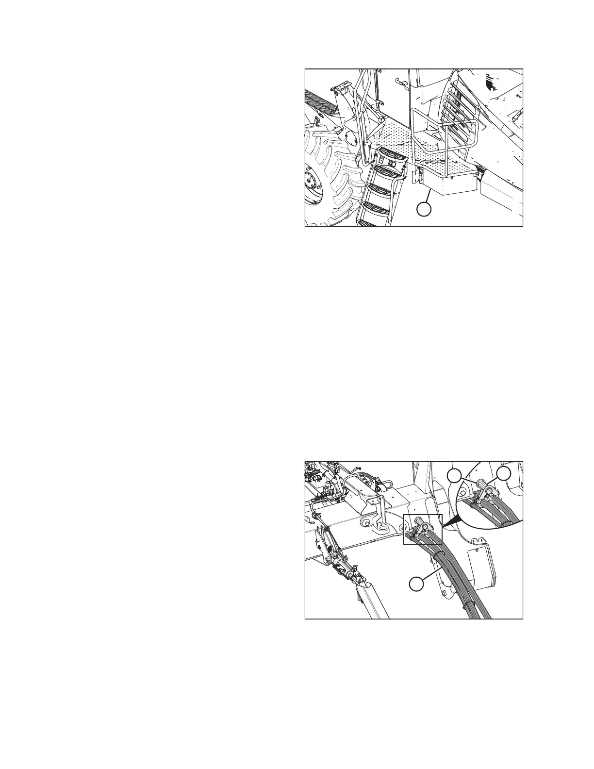
Figure 4.242: Hose Support Attachment
1. Retrieve hydraulic hoses (A) from the header and route the
hose bundle under the windrower frame.
NOTE:
Adding anti-seize compound to the hose holder pin will
make future removal easier.
2. Insert pin (B) into hole (C) in the windrower frame.
IMPORTANT:
Route the hydraulic hoses as straight as possible, avoiding
wear points that could damage the hoses. To prevent
abrasion damage, the hoses should have enough slack to
pass by the multicoupler bracket without contacting it. To
adjust the slack in the hoses, loosen the clamps below
pin (B), adjust the hoses, then retighten the hose holder.
OPERATION