215916 203 Revision A
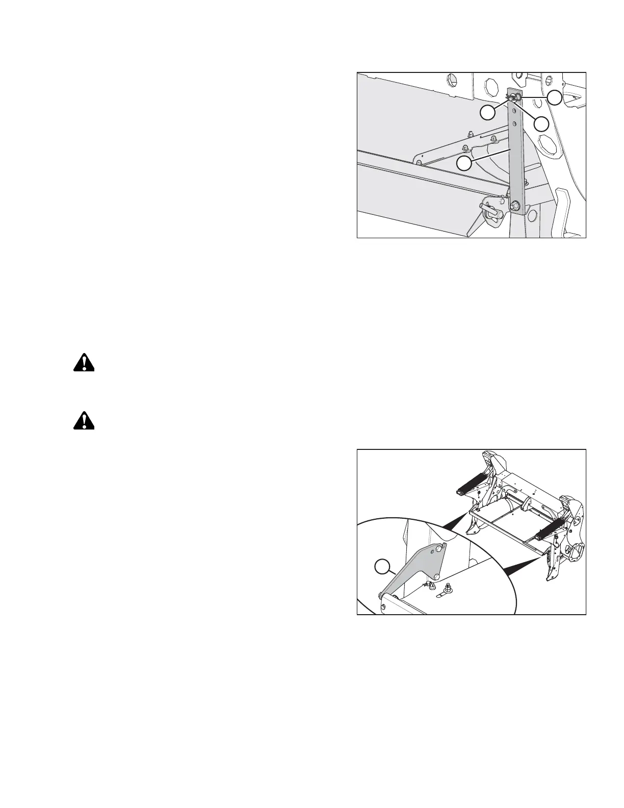
Figure 4.203: Rubber Strap Securing Forming Shield
onto Windrower Leg
3. Attach rubber strap (D) to straight pin (C) at the rear of the
windrower leg. Secure it with washer (B) and lynch pin (A).
4. Repeat Step 2, page 202 to Step 3, page 203 at the
opposite side of the forming shield.
Attaching R2 Series Rotary Disc Header
The windrower may have an optional self-aligning hydraulic center-link, which allows control over the vertical position of
the center-link from the cab. If the windrower is so equipped, the procedure for attaching an R2 header will be slightly
different.
DANGER
To prevent bodily injury or death from the unexpected startup of the machine, always stop the engine and remove the
key from the ignition before leaving the operator’s seat for any reason.
DANGER
Ensure that all bystanders have cleared the area.
Figure 4.204: Shield Mount Plates on Forming Shield
IMPORTANT:
When attaching an R216 SP Rotary Disc Header to an M1 Series
Windrower that has been previously configured for a D1X Series
Draper Header, ensure two shield mount plates (A)
(MD #307045) are attached to the windrower and forming shield.
1. Shut down the engine, and remove the key from the ignition.
OPERATION